P350 Kit
1. Preparation before Assembly
1.0 Introduction
READ THE INSTRUCTIONS BEFORE ASSEMBLY!!
The P350 features a modular design and comprises the following main modules:
-
Frame
-
Zdrive
-
Gantry
-
Tool Head
-
Heated Bed
-
Enclosure(optional)
-
Each can be pre-assembled separately.
-
However, we recommend assembling in the following order:
-
Frame, Zdrives, Gantry, Tool Head, Heated Bed, Electronics.
2. Frame
2.0 Check before the assembly
2.0.1 Printed parts
-
The printed parts required in this section contain:
-
frame_down_left_front_corner (1pcs)
-
frame_down_right_front_corner (1pcs)
-
frame_down_left_rear_corner (1pcs)
-
frame_down_right_rear_corner (1pcs)
-
frame_up_left_front_corner (1pcs)
-
frame_up_right_front_corner (1pcs)
-
frame_up_left_rear_corner (1pcs)
-
frame_up_right_rear_corner (1pcs)
-
frame_rail_support (4pcs)
-
Fixture: MGN12 fixtures (2pcs)
-
Fixture: corner fixtures (4pcs)
-
Metal Parts:
-
T-Slot 3030 Aluminium Profile (12pcs in total)
-
MGN12 450mm with MGN12H Blocks (4pcs)
2.0.2 Bolts and nuts
-
The bolts and nuts required in this section contain:
-
M8 x 16 Button Head Cap Screws (16pcs)
-
M5x30 Screw (16pcs)
2.0.3 Tools
-
The tools required in this section contain:
-
Hex(5mm)
-
Hex(4mm)
2.0.4 Workspace requirements
- The recommended working space needs to be as flat as possible. A minimum 2m x 1m space is recommended for placing the parts and tools
2.0.5 Aluminium:
- Take out the extruded Aluminum from the Frame box carefully.
2.1 Bottom Frame
2.1.0 Assemble
-
Note that the key to a good and correctly built frame is flatness and alignment.
-
In this section, the flat surface you have and the printed part will work as fixtures. They will help you align the frame.
-
Here are the fixtures you will need:
-
(pic)
-
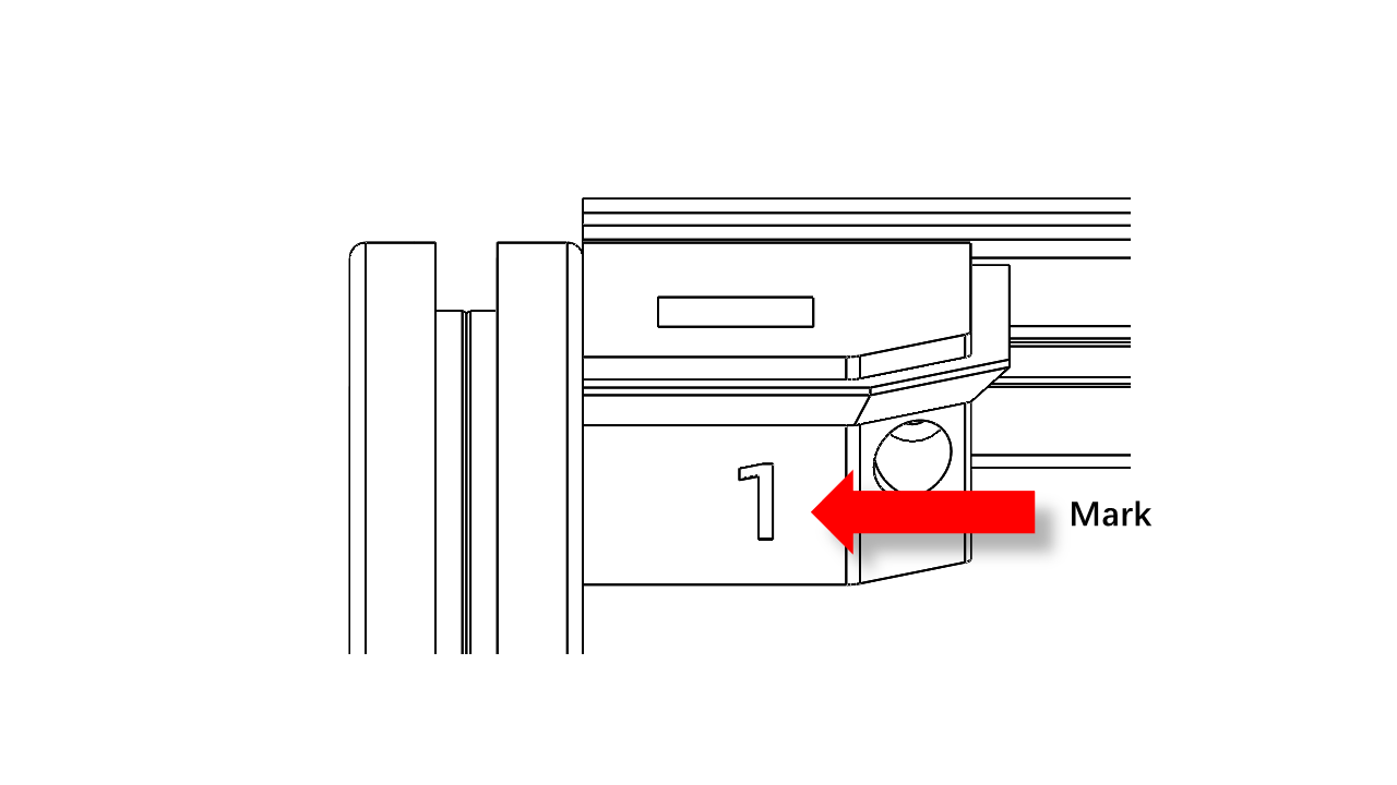
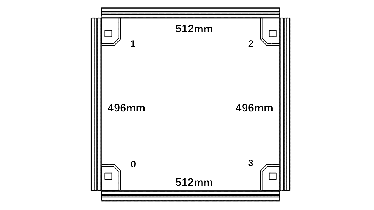
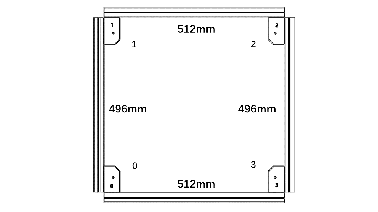
First, take and place the parts for the bottom frame as follows. Note that there are marks on the printed parts to indicate the orientation.
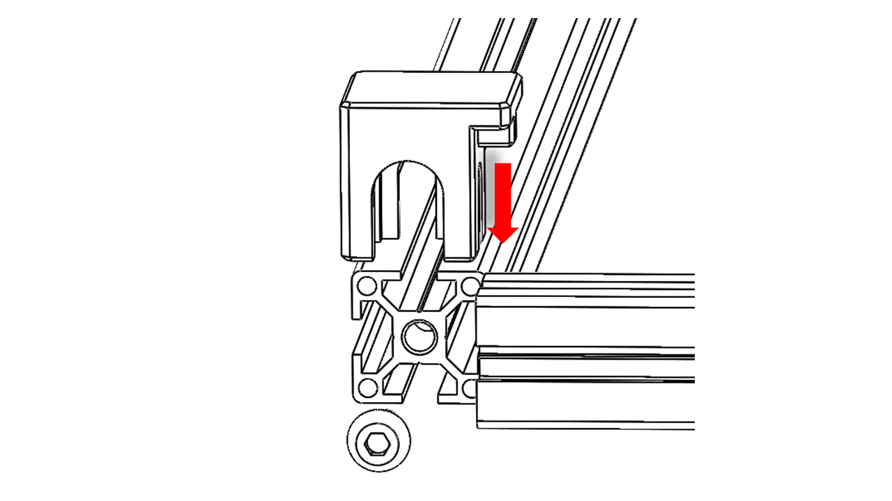
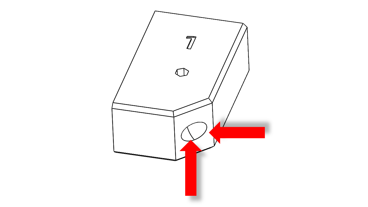
- Use the fixture to help you align the Aluminium profile. The boss on the fixture should fit nicely into the slots of the profiles.
- Then put the M8 screws on. Tighten the screws against the table using the four corner fixtures.
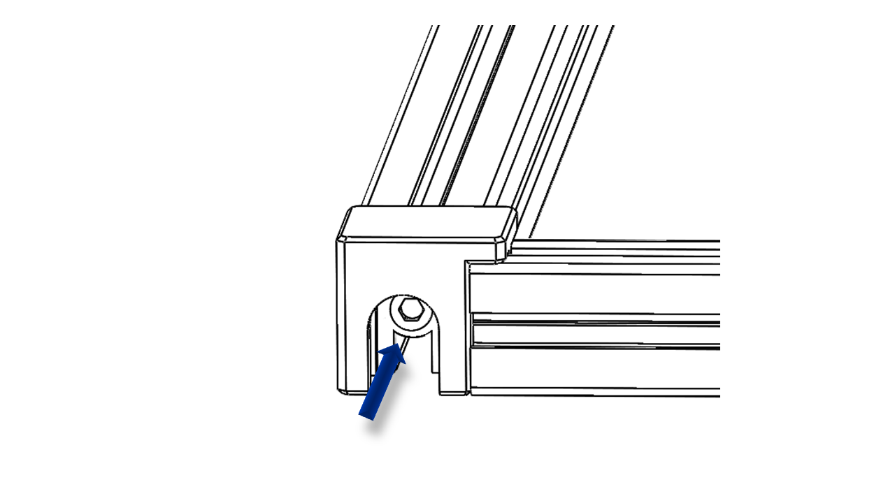
- Insert an M5x30 screw into the printed parts, and attach the T-nut (3030 M5).
-
For T-nut, you should always make sure it is turned 90 degrees correctly before tightening.
-
You can check this video to see how it is done.
- A fully tightened T-nut should look like this.
-
Connect the printed part to the lower frame.Press the profile tightly against the desktop to tighten the corner printed parts, then loosen the M8 screws by about 90 degrees and pull out the fixture. Repeat this for all four corners.
-
Remember to remove the fixture before you proceed to the next step.
-
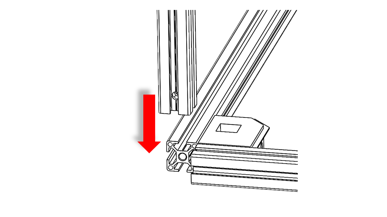
Slide the vertical frame into the corner we just assembled. You should align the bottom frame with the profile end surface with a level table surface.
-
Then tighten the M8 screws. Note that you should tighten both screws in turn to ensure stress distribution.
-
Repeate this for all four corners.
2.1.1 Check
- Once you are done, push the bottom frame against your flat working space. It should not bump or make noises when you apply force to each corner.
2.2 Upper Frame
2.2.0 Assemble
- First, take and place the parts for the upper frame as follows. Note that there are marks on the printed parts to indicate the orientation.
-
Use the fixture to help you align the Aluminium profile. The steps should fit nicely into the slots of the profiles.
-
Then put the M8 screws on. Tighten the screws against the table using the four corner fixtures.
-
Insert an M5x30 screw into the printed parts, and attach the T-nut (3030 M5).
-
Connect the printed part to the upper frame. For T-nut, you should always make sure it is turned 90 degrees correctly before tightening.
-
Connect the printed part to the lower frame. Press the profile tightly against the desktop to tighten the corner printed parts, then loosen the M8 screws by about 90 degrees and pull out the fixture.
-
Repeat this for all four corners.
-
Remember to remove the fixture before you proceed to the next step.
2.2.1 Check
-
Make sure the upper frame sit steady on the flat surface.
-
Slide the vertical frame into the corner we just assembled. You should align the bottom frame with the profile end surface with a level table surface. Then tighten the M8 screws. Note that you should tighten both screws in turn to ensure stress distribution.
- Repeate this for all four corners.
2.3 Frame Assembly
2.3.0 Main Frame
-
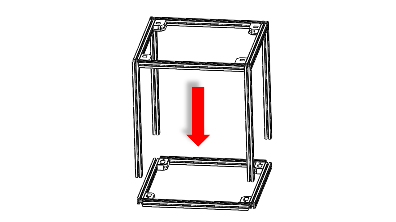
Now, put the lower frame with vertial beam upside down.
-
Slide the vertical beam into the four corners of the upper frame. Once you are done, the frame should fit nicely.
-
Now tighten the M8 screws in turn, making sure each screw applies relatively the same torque.
2.3.1 Check
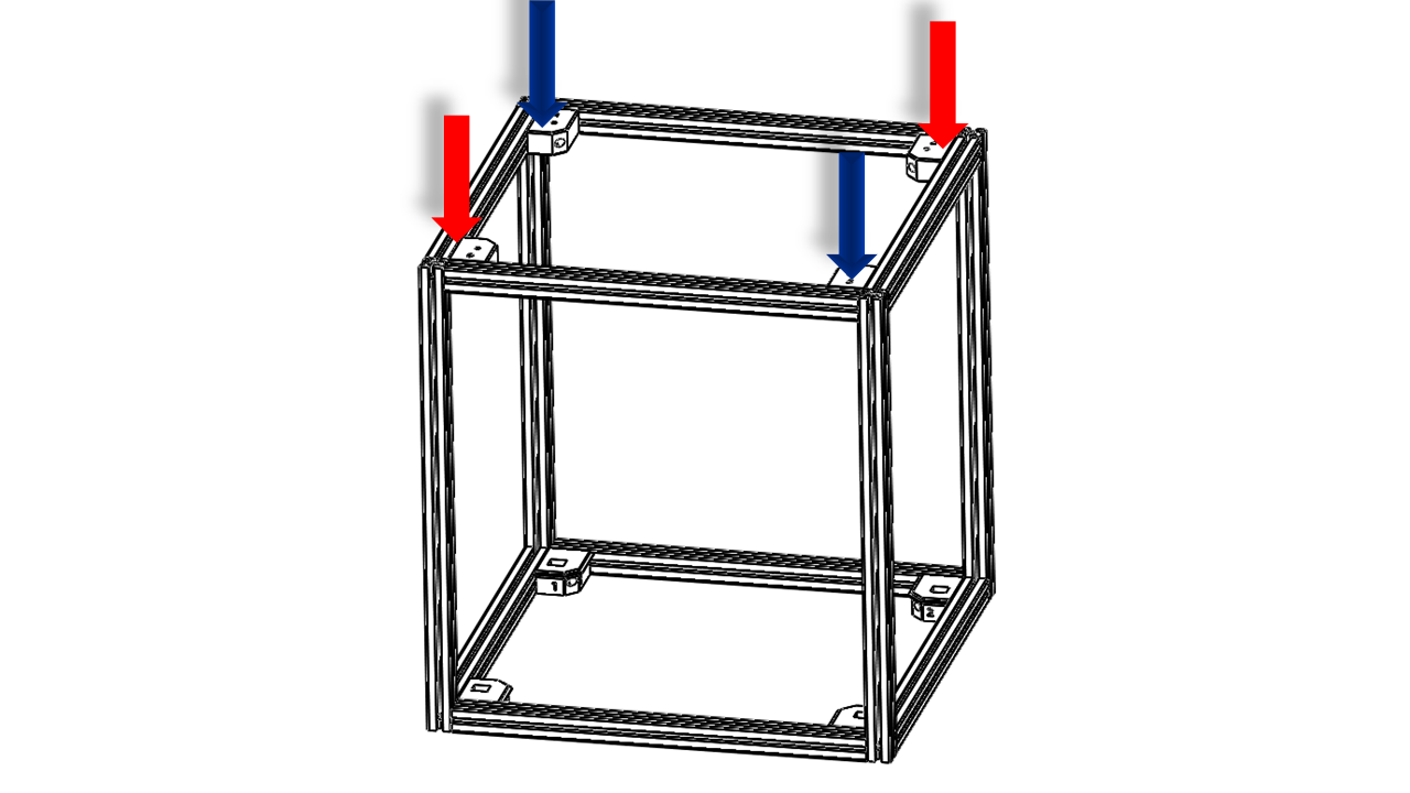
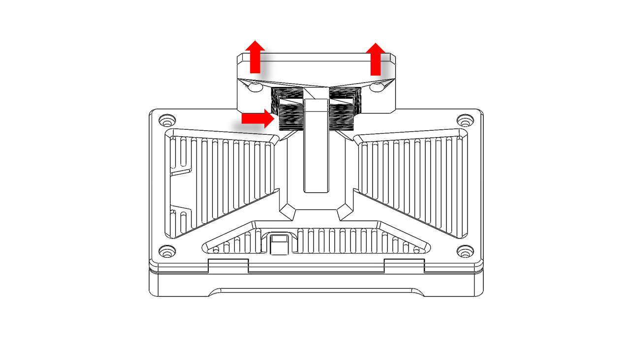
- Now check the frame. All the screws must be fully tightened. Put the frame in its initial orientation. Apply force on each corner of the upper frame against the flat surface as shown .
- The frame should not have any significant bumps or make any noise. Note that the profile straightness and torsion issues can cause slight unevenness. This is fine.
2.3.2 Linear Rails
- Linear rails for the Z axis are very important for a 3D printer. We will use jigs and printed parts to ensure the alignment.
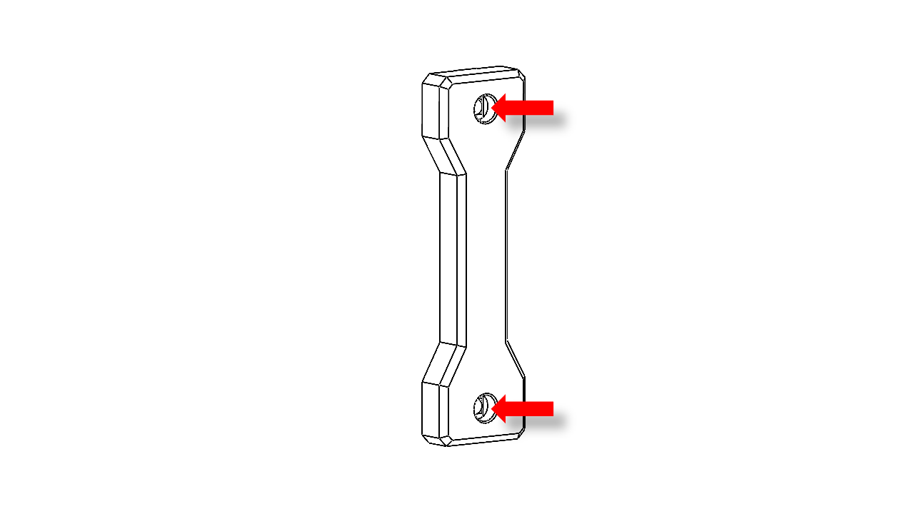
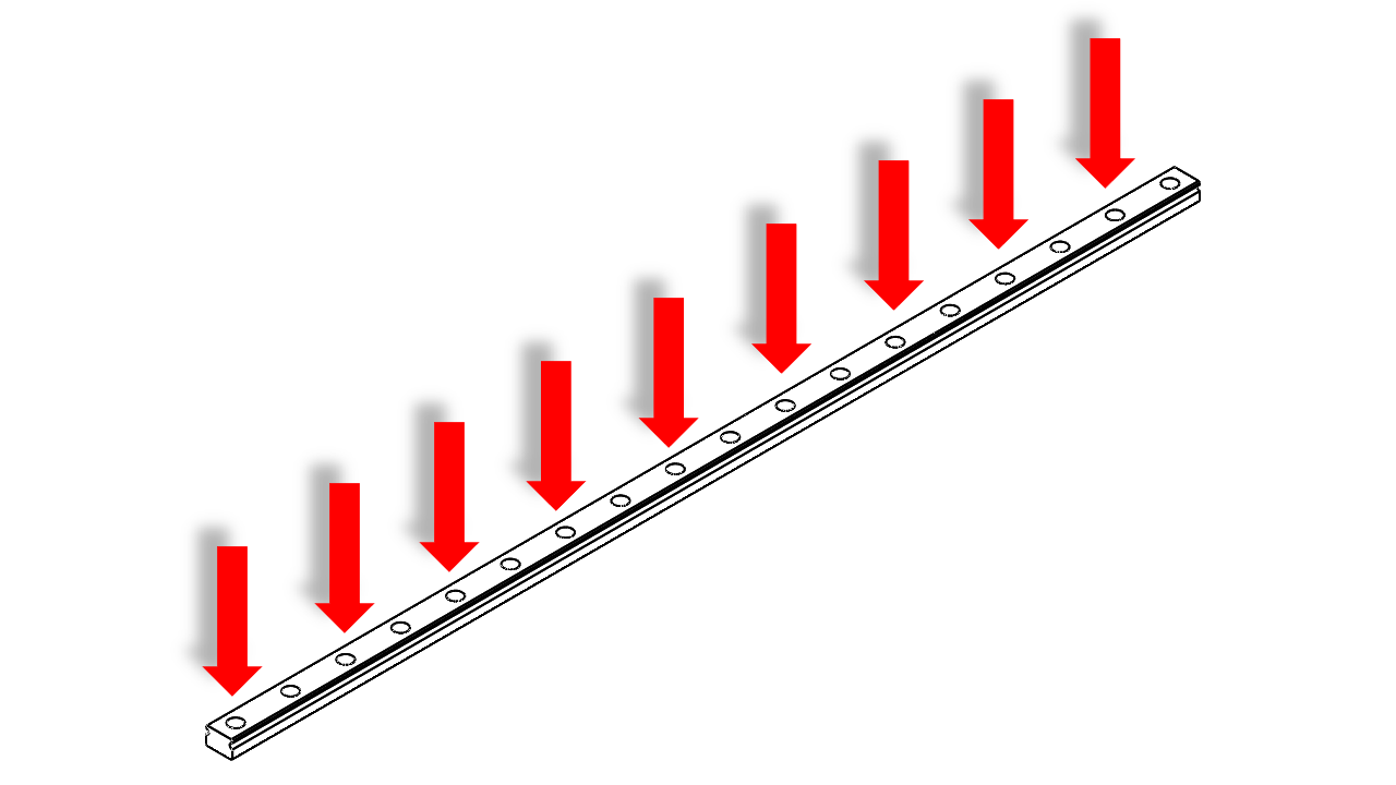
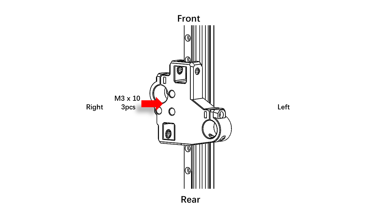
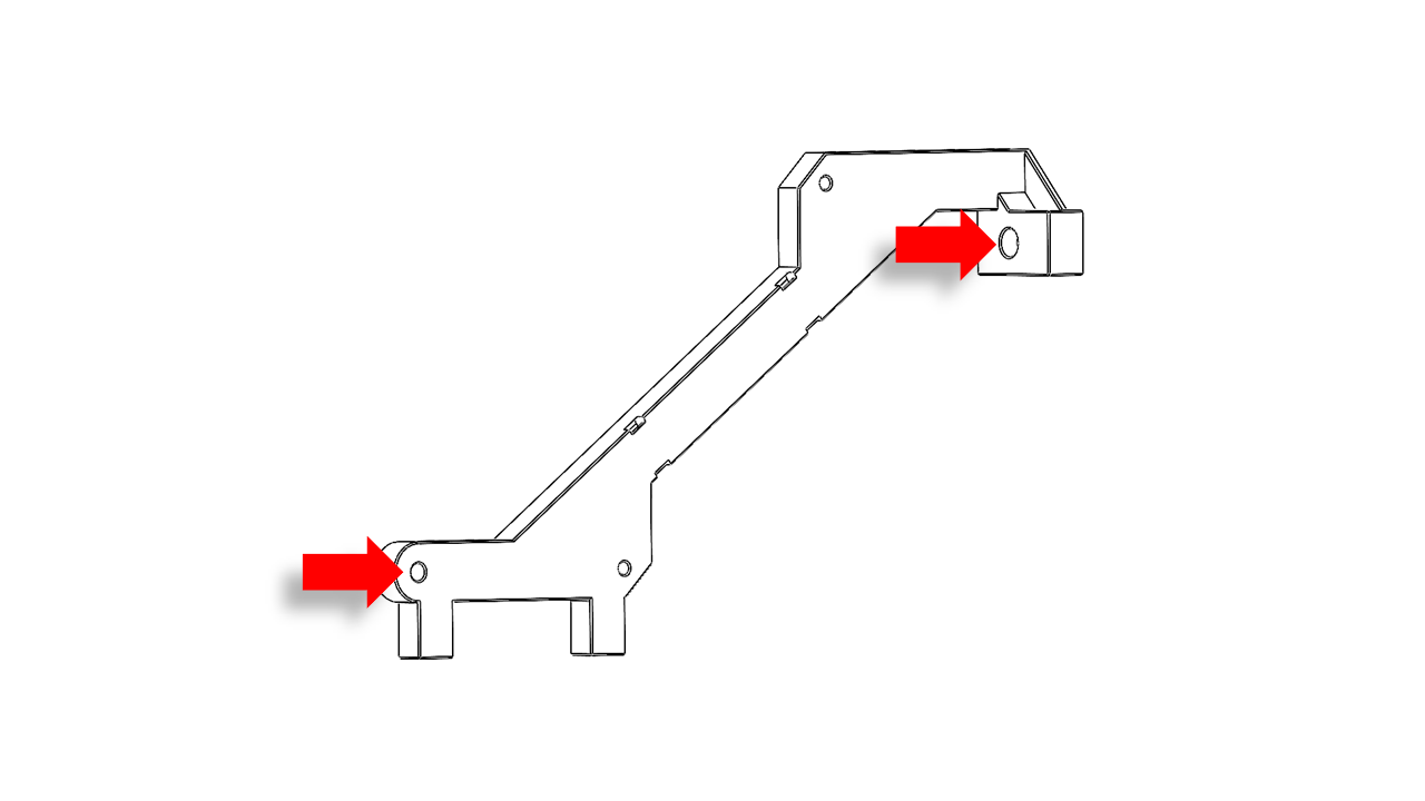
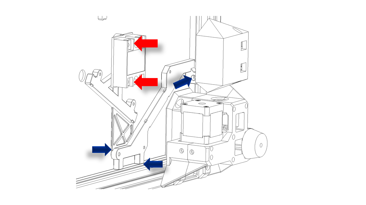
- First, attach the M3x10 screw and T-nut to the rail support. This part can determine the position of the rails.
- Attach the rail support against the bottom of the frame as shown. Make sure the lower surface is directly against the bottom profiles.
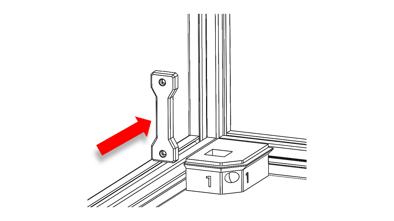
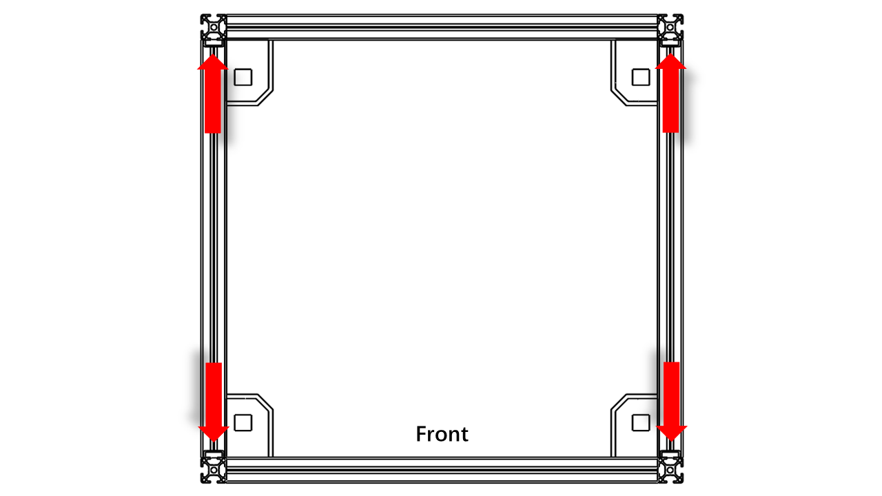
- Note that the rail support should be attached to these locations.
-
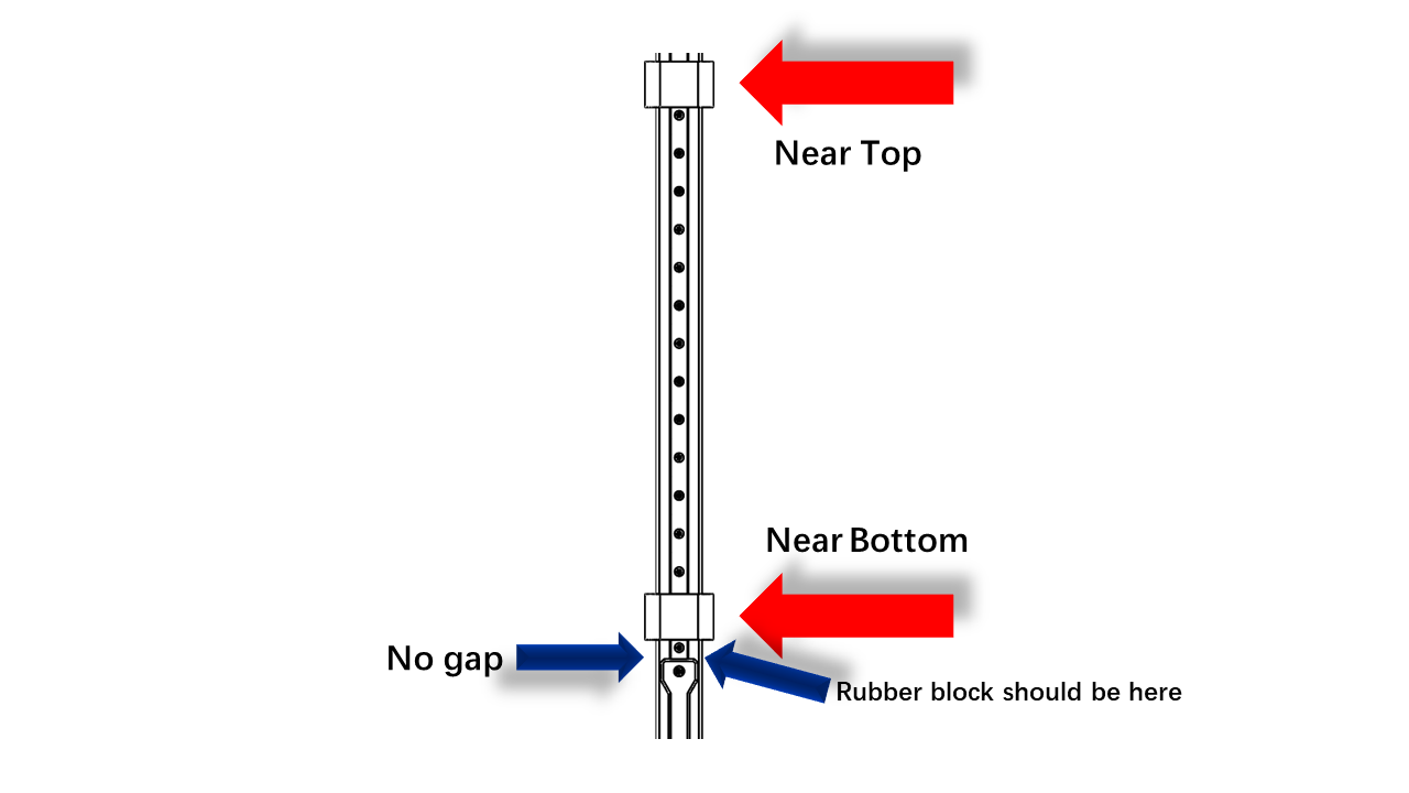
Now attach the M3x10 screws and T-nuts (3030 M3) on the rail as shown in the picture. Leave one empty and one placed. If the block or rubber insert blocks your operation. Slide them away and reinsert the rubber blocks at the end of the rail.
-
Do not let the MGN12 Block drop out!
-
To install the linear rail, you will need the printed fixture. Get them in advance.
-
Now, put the rail against the frame as shown and use both of the printed tools to clamp the rail on the frame for alignment.
- Tighten the M3 screws in turn. Note that these are T-Nuts. For T-nut, you should always make sure it is turned 90 degrees correctly before tightening. You can check this video to see how it is done.
2.4 Z-Drive
2.4.0 Pre-insert the nuts
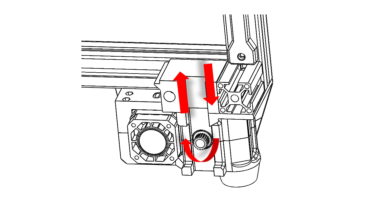
- Attach the M3 hex nuts to the screws and push the nuts until they reach the end. Do this for all Z-drive printed parts. Note that each Z-drive module has a mark on it. They are in pairs, so make sure we do not mix them.
Insert the M5 nut and then use the screw-pulling technique. Screwed the nut in tightly to embed and then remove the screws
2.4.1 Assembly
- First, put the GT2-188mm timing belt on the largest wheel on the gear module.e
-
Take the Z driver gear module and put it inside the slots. It should fit nicely. Note the orientation and then put the upper part as shown.
-
Insert the long M3x50 screws as shown and tighten this module. Check if the GT-2 beltsares already on the gears. Tighten all screws properly. Rotate the gears inside. It should spin without any friction.
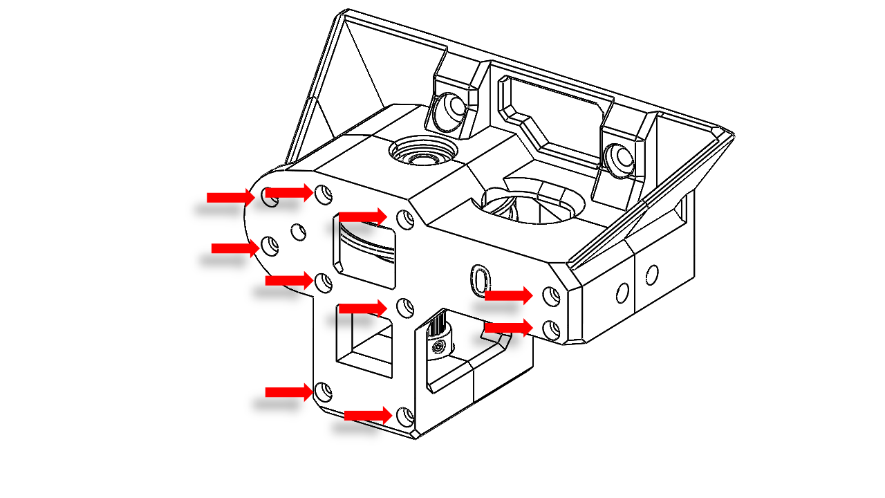
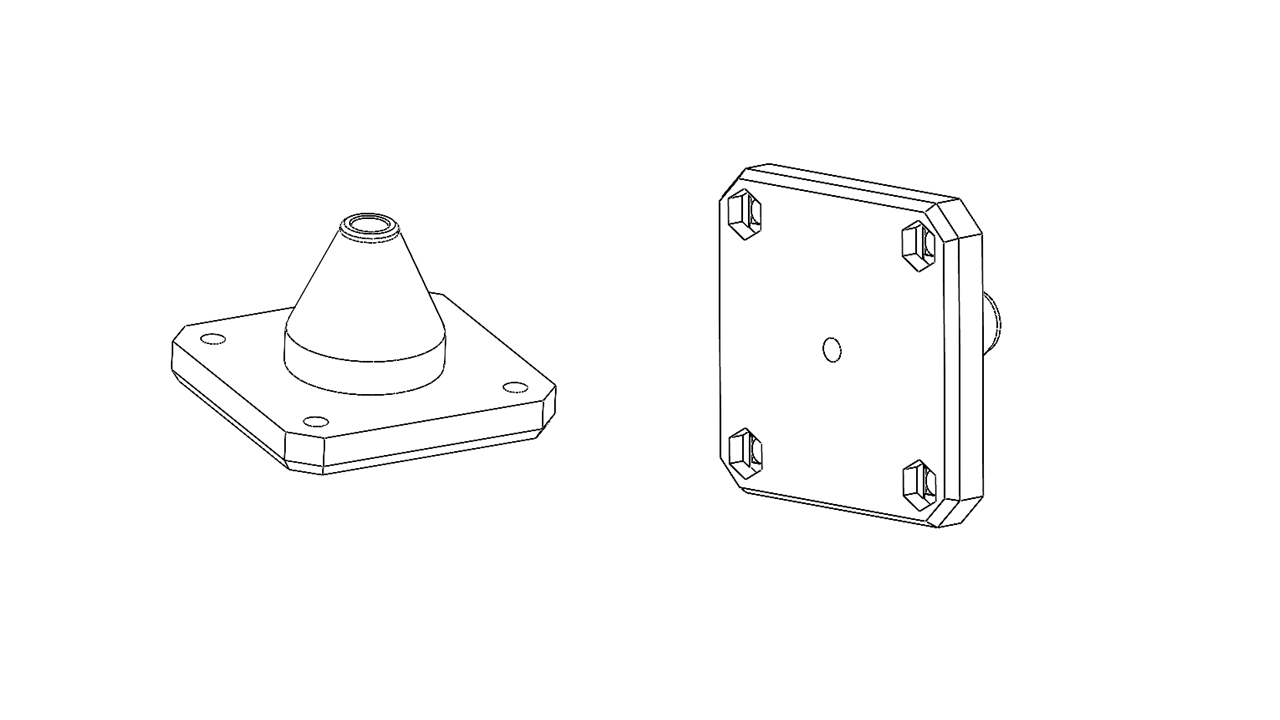
- Now it's time to attach the footpad. Use an M5 x 20 screw as shown.
Now we can prepare the motors. First, we need to insert M3 nylon insert lock nuts at the motor mount printed parts as shown. Attach the nut on the M3 screw first anduses it as a guide, then press the nut in with a 4mm hex tool. Remove the screw when you are done.
-
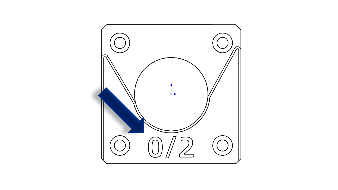
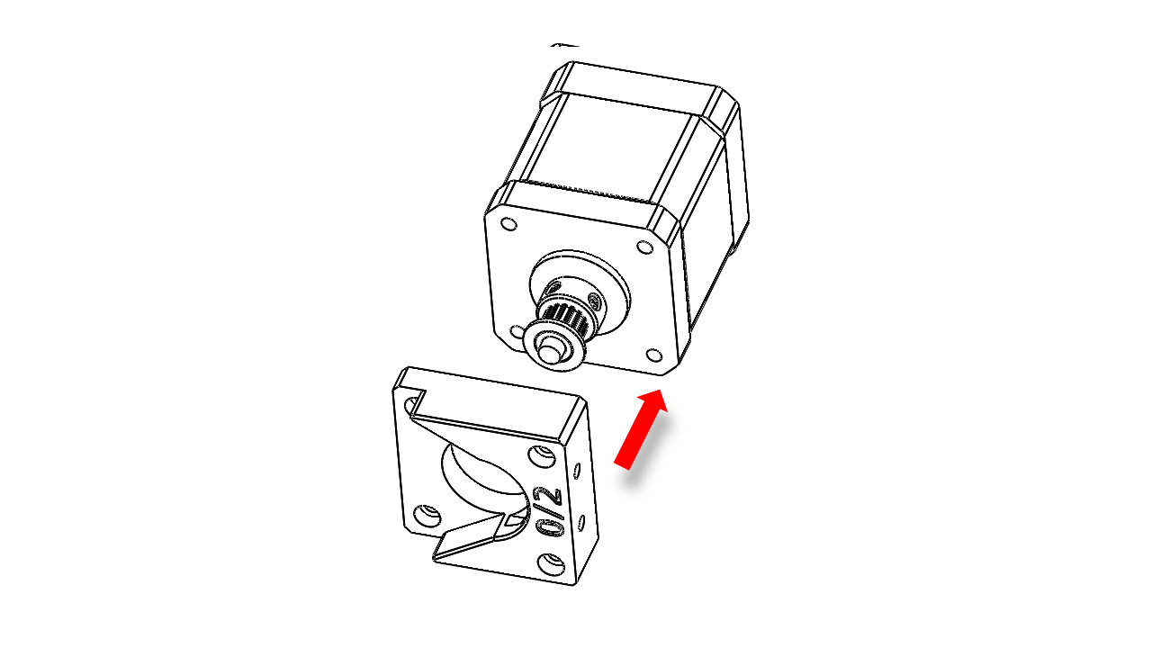
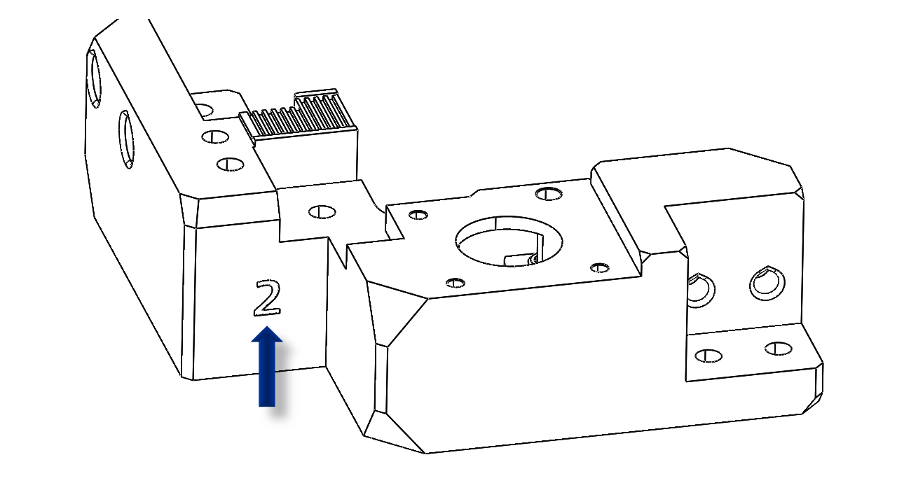
Note that each motor mount is not the same. This mark shows the pairs it should have. This one, for example, can be matched with #0 or #2 Z-drivers.
-
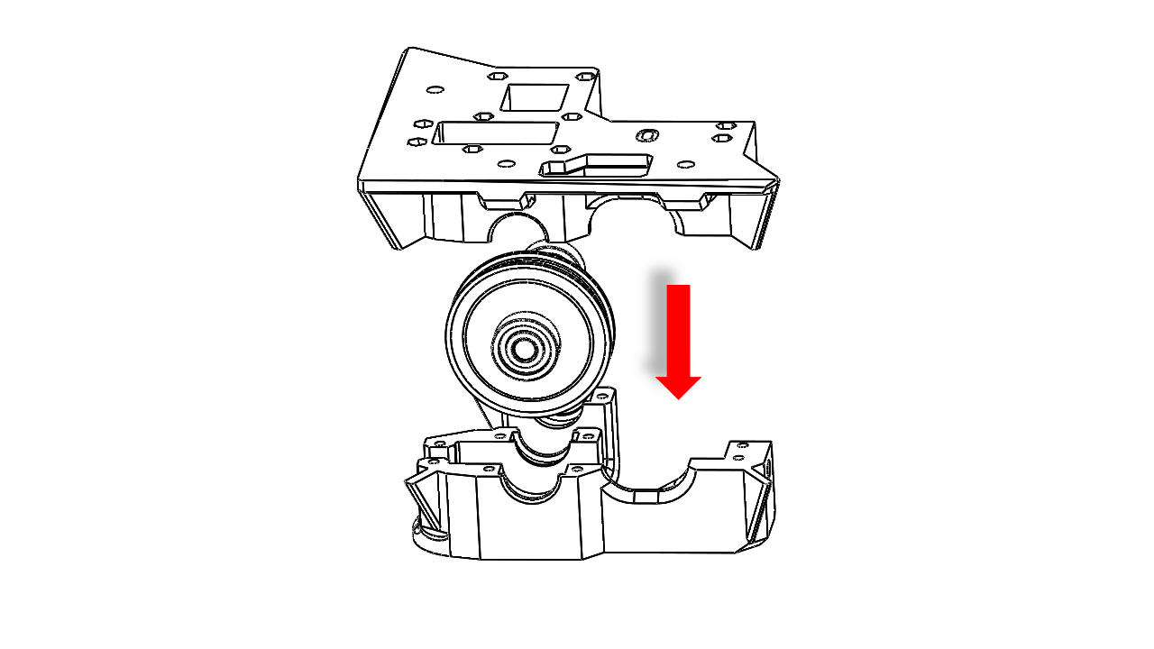
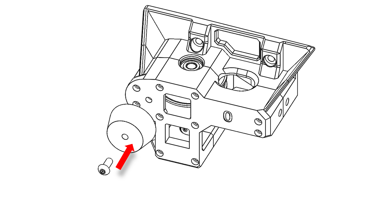
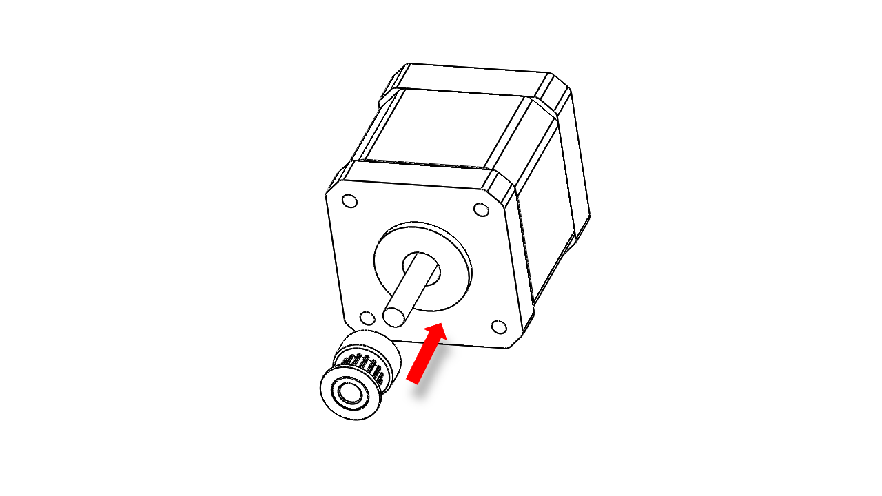
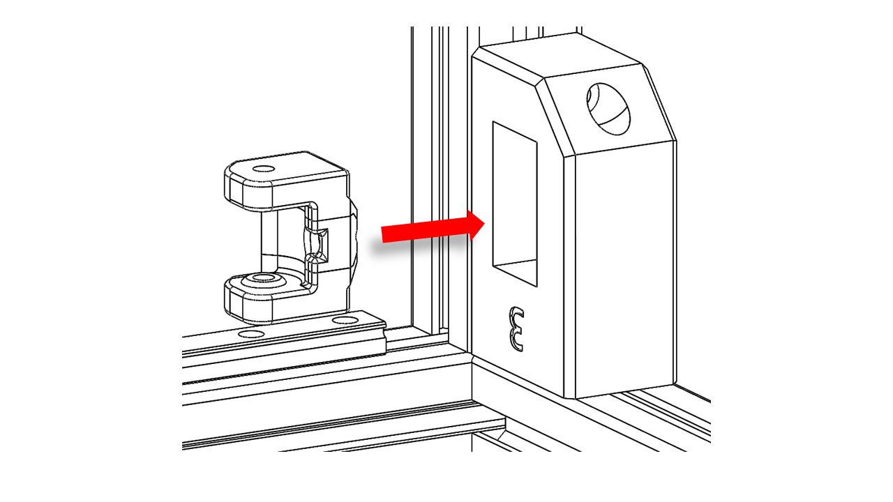
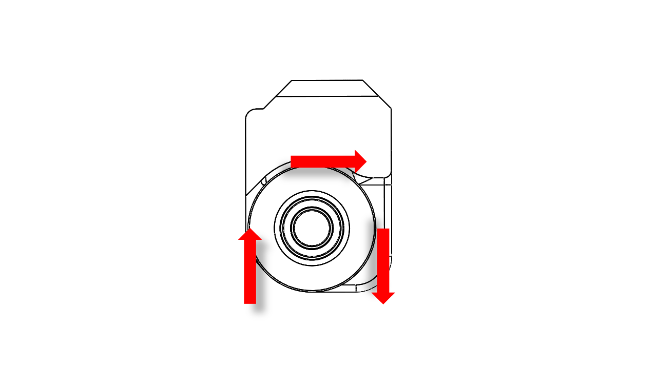
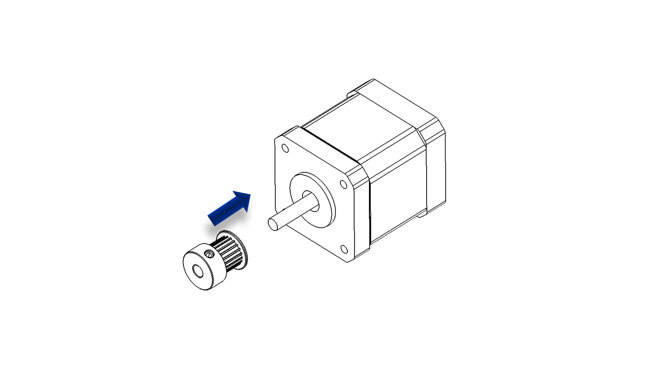
Now put the driving pulley on the motor. Use the jig to help you locate the correct position.
Then you should attach the motor mount to the motor as shown with M3 x 8 and M3 x 16 screws. Note that the motor wires should be facing upwards.
-
The Z motors will be attached later. Do not install them at this point.
-
Repeat this for all four Z-drives; be careful with the matching.
2.4.2 Attach the Z-drive
-
Now, put the frame upside down,n as we are going to attach the Z-drive module.
-
Pre-insert M5 spring nuts into the profiles at the bottom of the frame. You may use the Z-drive module as a jig to locate where these spring nuts should be.
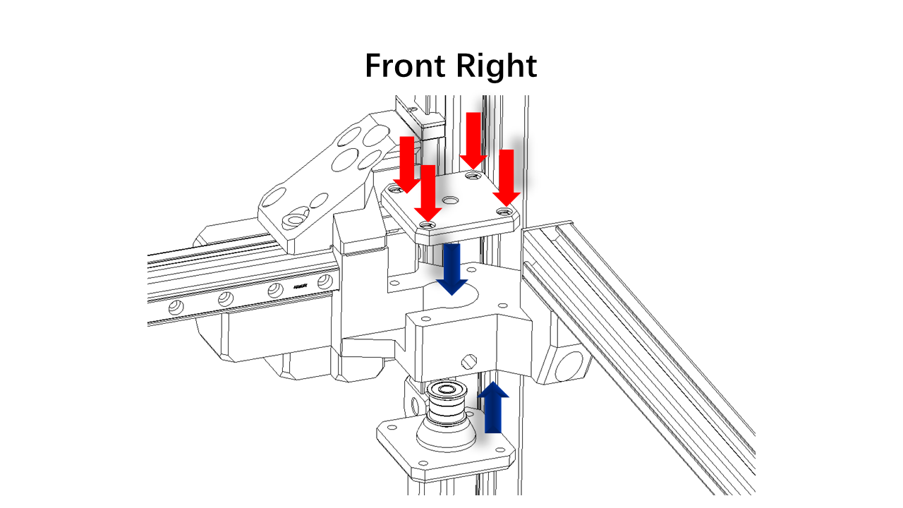
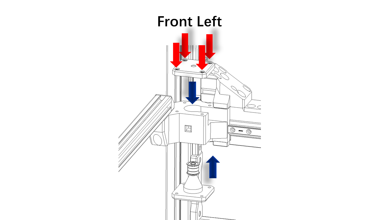
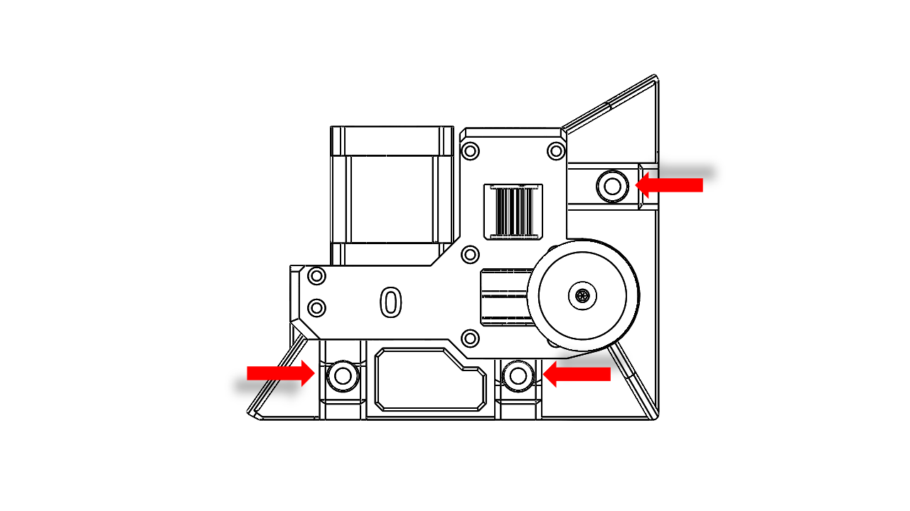 - Fix the Z-drive module with M5 x 16
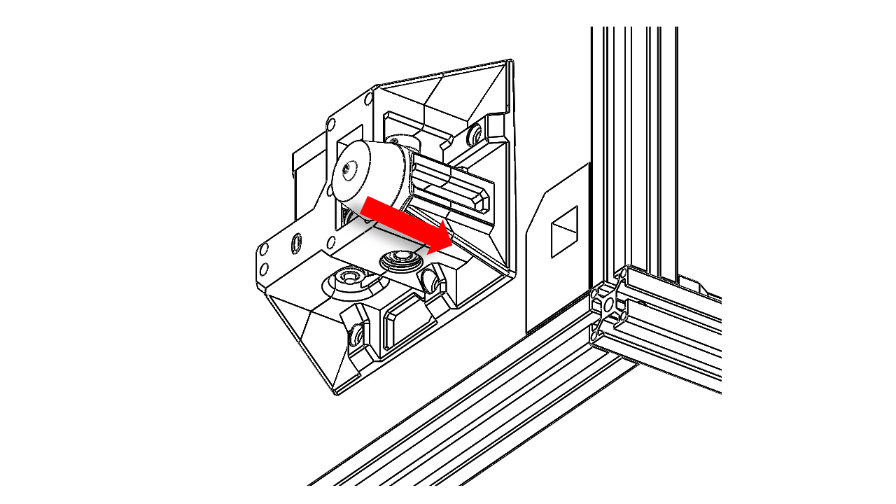
Pass the Z belt as shown. Leaving enough length on both ends.
3. Gantry
3.1 The main Gantry
3.1.0 Pre insert the nuts on printed parts
- All gantry parts have marks on them, which should match each other.
-
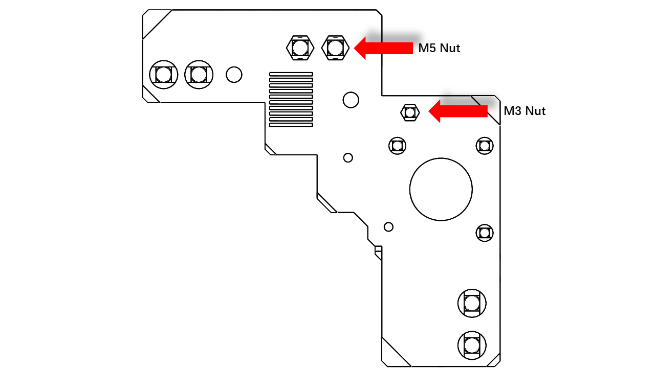
Insert M5 and M3 nuts on each of the gantry main parts (the four big ones)
 .
. -
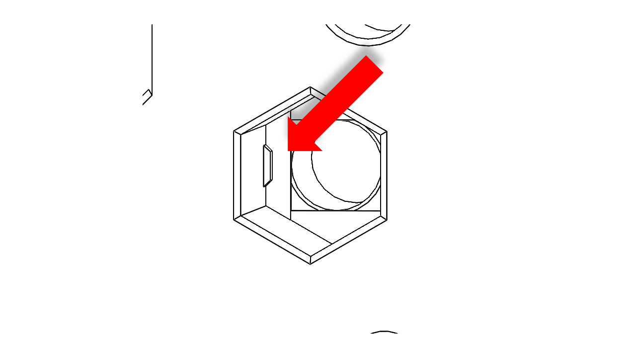
There are bumps at the end of the M5 nut holes. This is to make sure the M5 nut stuck nice and tightly. For M5 nuts, use the screw pulling technique to make sure they reach the end. Once you are done, they should not fall out due to gravity.
 .
.
- Do this for all four gantry main body parts.
3.1.1 Prepare the Z belts
- Take out the Z belts, put them aside for later use
3.1.2 Prepare for assembly
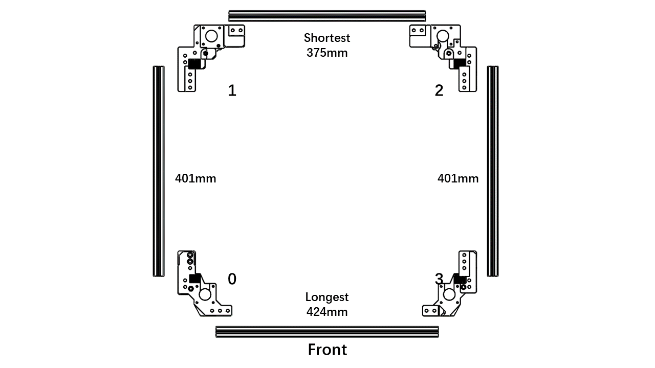
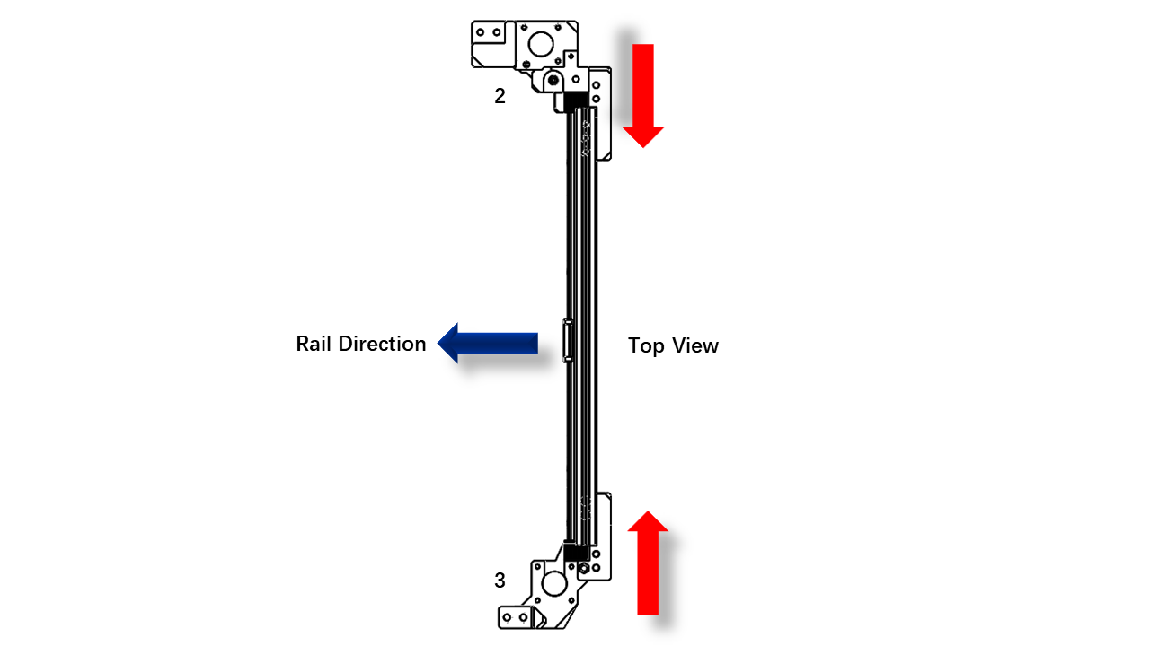
- Find the 2020 profiles for the gantry; there are four of them. Place them as the picture shown. Make sure the marks match the locations. Note that the gantry has an asymmetrical design.
 .
.
3.1.3 Install the Y rails
- First, attach the M3x8 screws and T-nuts to the rail as shown in the picture. Leave one empty and one placed. If the block or rubber insert blocks your operation. Slide them away and reinsert the rubber blocks at the end of the rail to prevent the block drop off. Dropping out the sliding blocks may result a permenet damage to the linear rail!
.
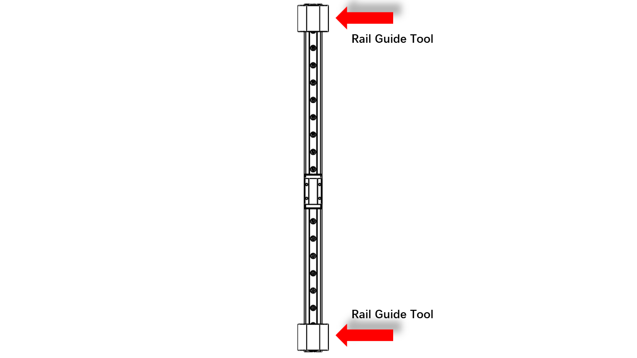
- Now place MGN9 rail guide jig at both ends to help you align the rail to the correct position.
 .
.
- Note that the rail should be centered, and it is slightly shorter than the profile. Neither end of the rail should stick out of the 2020 profile.
 .
.
- Tighten the T-nut properly. For T-nut, you should always make sure it is turned 90 degrees correctly before tightening.
-
You can check this video to see how it is done.
-
Do this for both 401mm profiles.
3.1.4 Assemble the left part of the gantry (Part 1/0)
- First, we need to insert the spring nut.
- This isana M5 spring nut for 2020 profiles. Note that it is not symmetrical. Thus insert nuts can be a bit tricky.
 .
.
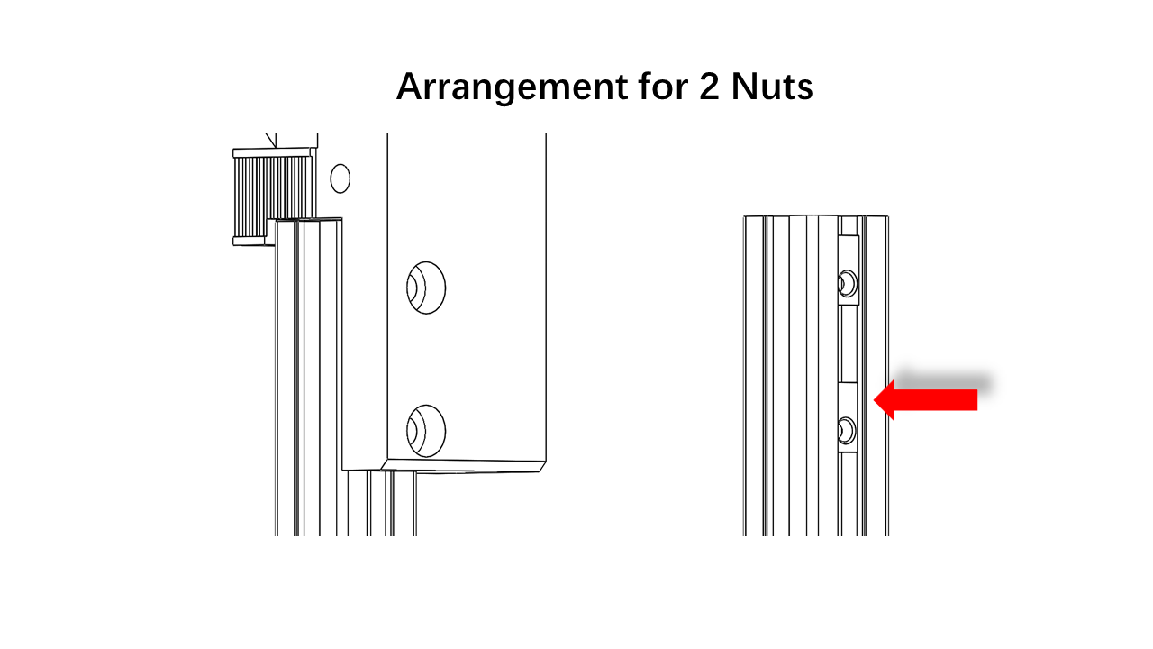
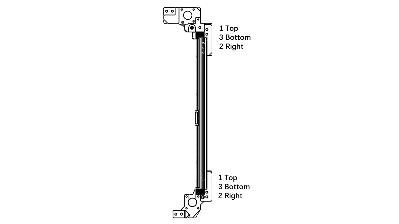
- You should insert the correct number of nuts on the profiles to secure them on the printed parts. For 2 nuts, we recommend that you insert them as shown below.
 .
.
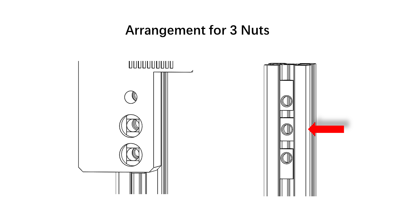
- For the situation with 3 Nuts, you should replace the middle one with a regular T-nut. Otherwise, there is not enough space.
 .
.
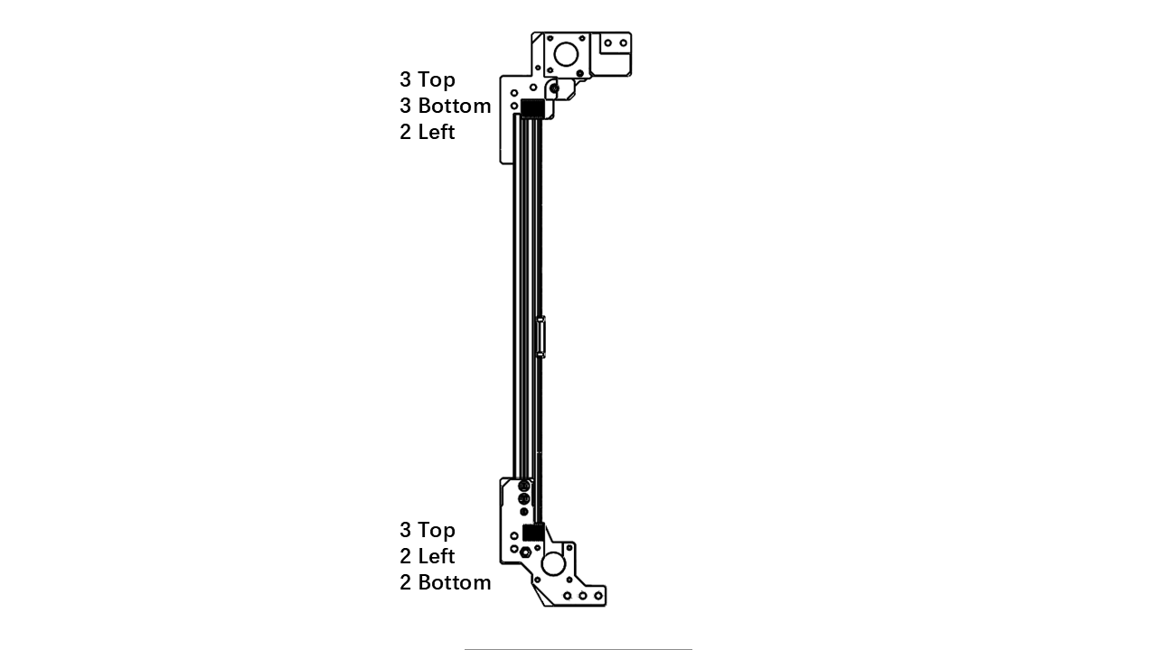
- The amount of nuts required is listed as shown. Follow the arrangement we have earlier. Proceed after you have all the nuts inserted.
 .
.
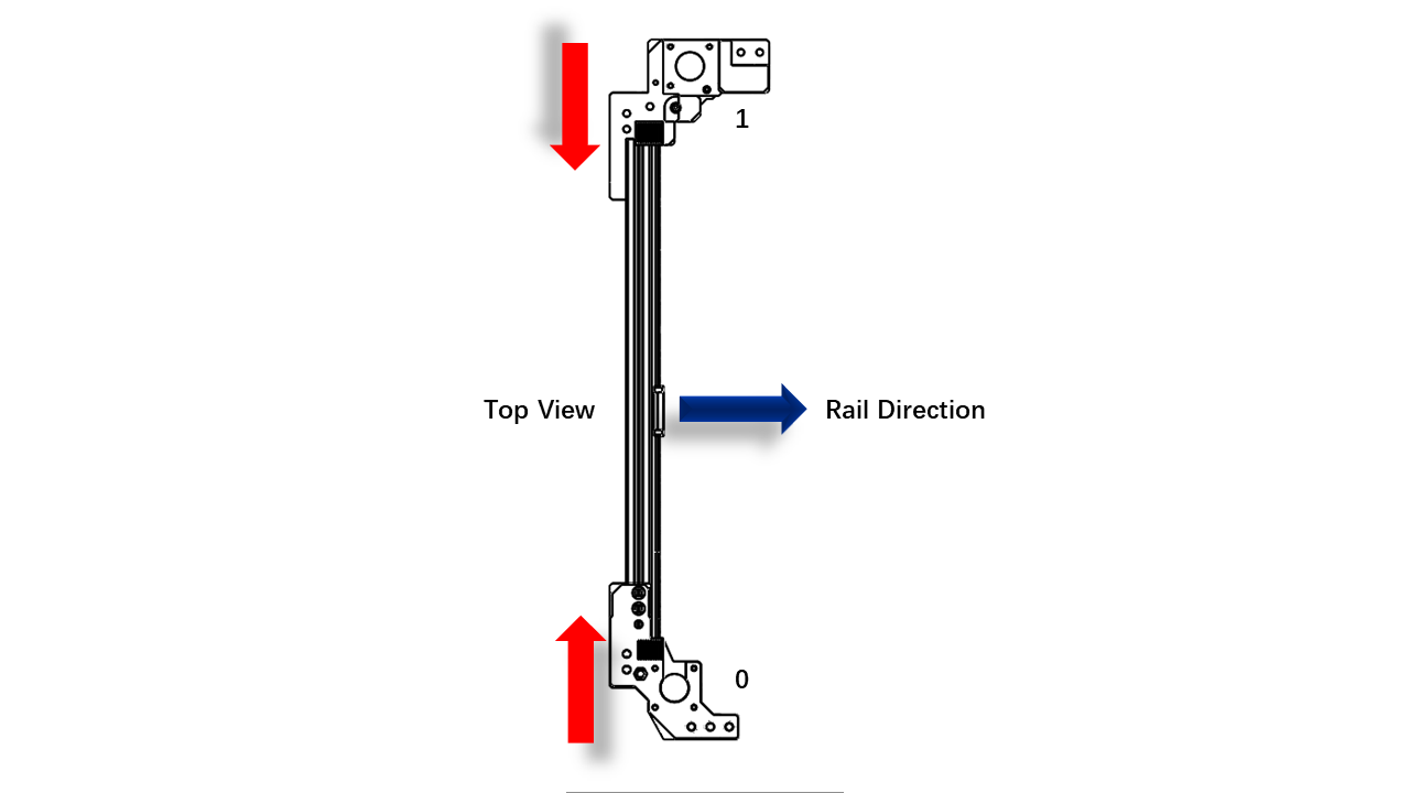
- Once you are done, insert the 2020 profilesinton these locations. Use a hex to help you locate nuts so they can align with the holes on the printed parts.
 .
.
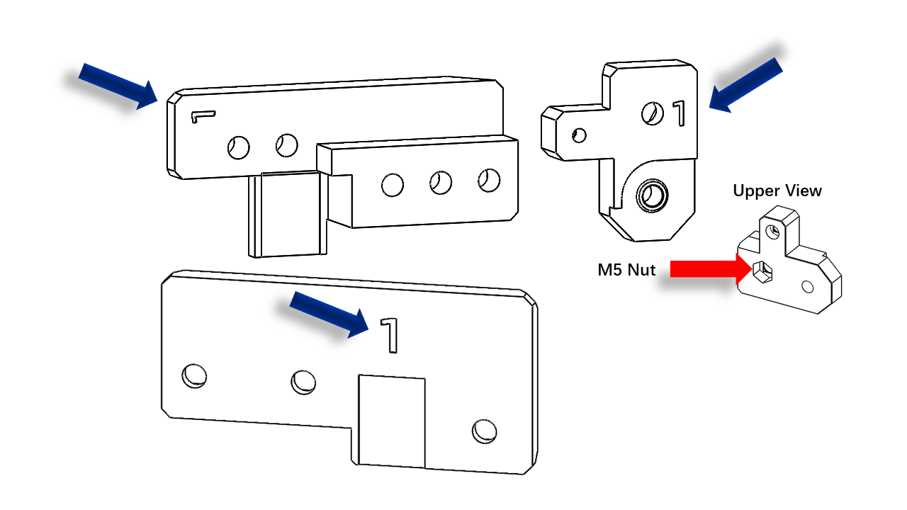
- Next, we need these printed parts labeled with 1/0
 .
.
 .
.
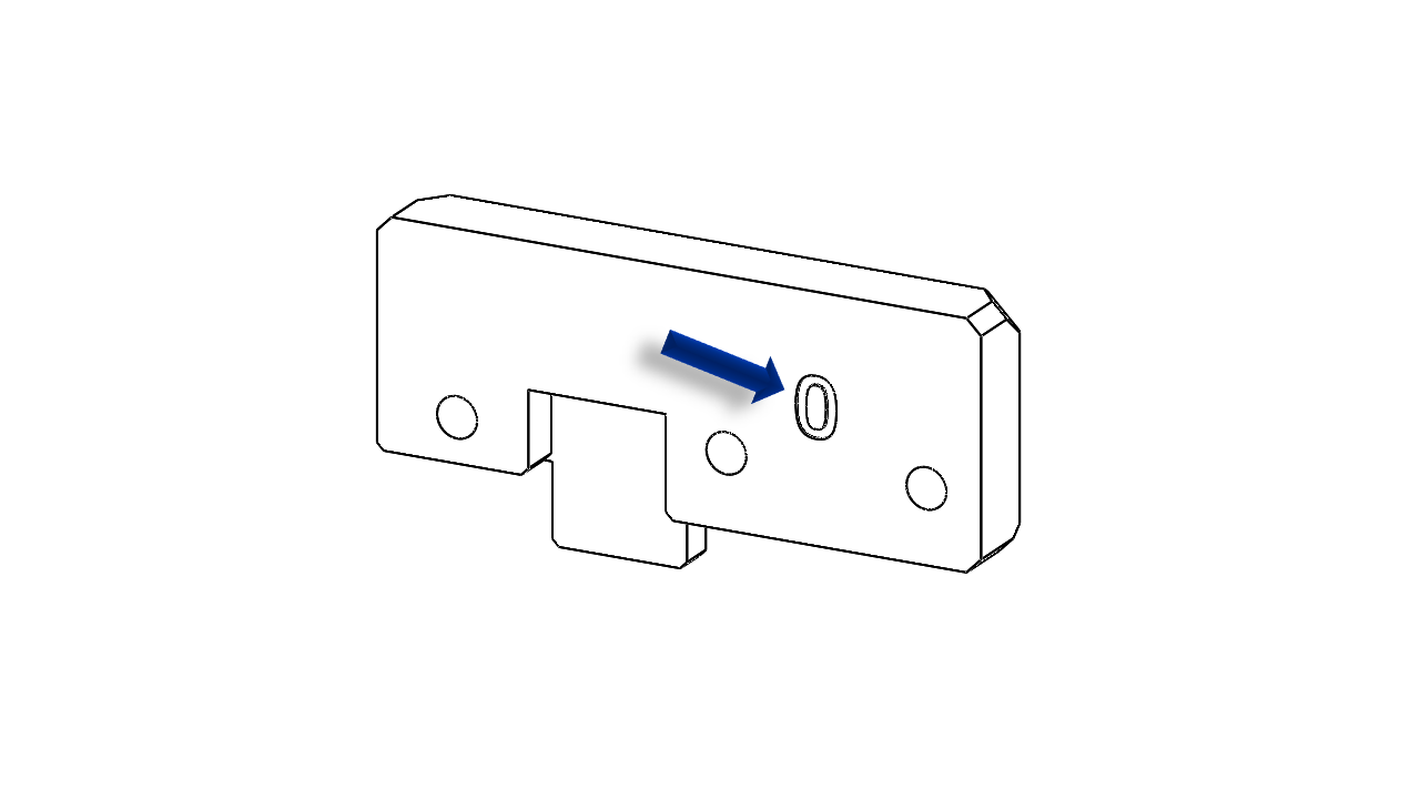
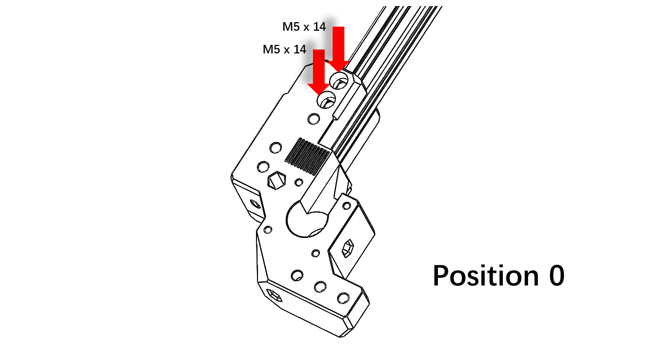
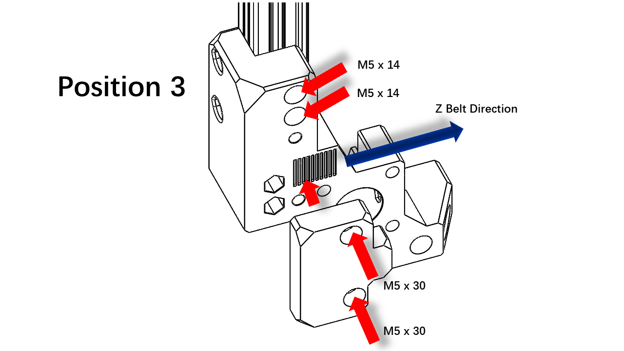
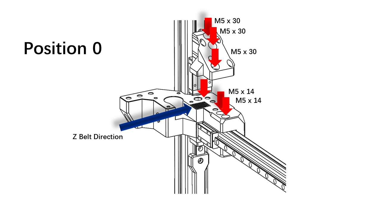
- Clip the Z belt to the bottom of Part 1. Note that the Z belt must match all slots on the parts. Use M5 x 14 to fix the bottom Z belt clip. Insert the M5 x 3050 Screw for later use.
 .
.
- Then install the upper part as shown. This M5 nut is for the M5 x 30 screw in the previous step.
 .
.
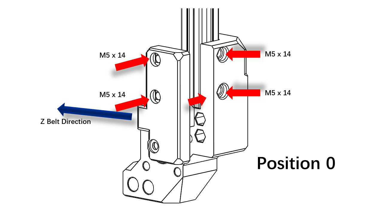
- Clip the Z belt to the bottom of Part 0. Note that the Z belt must match all slots on the parts. Use M5 x 14 to fix the bottom Z belt clip. Use M5 x 14 to fix the profile as shown.
 .
.
- Use M5 x 14 to fix the upper part of the profile as shown. The most bottom scerw is M5 x 30.
 .
.
3.1.5 Assemble the right part of the gantry (Part 2/3)
- The amount of nuts required is listed as shown. Follow the arrangement we have earlier.
- Proceed after you have all the nuts inserted.
 .
.
-
Once you are done, insert the 2020 profiles into these locations. Use a hex to help you locate nuts so they can align with the holes on the printed parts.
 .
. -
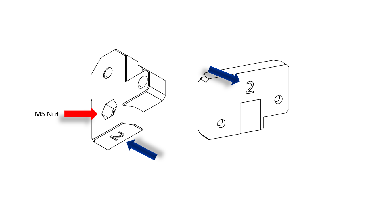
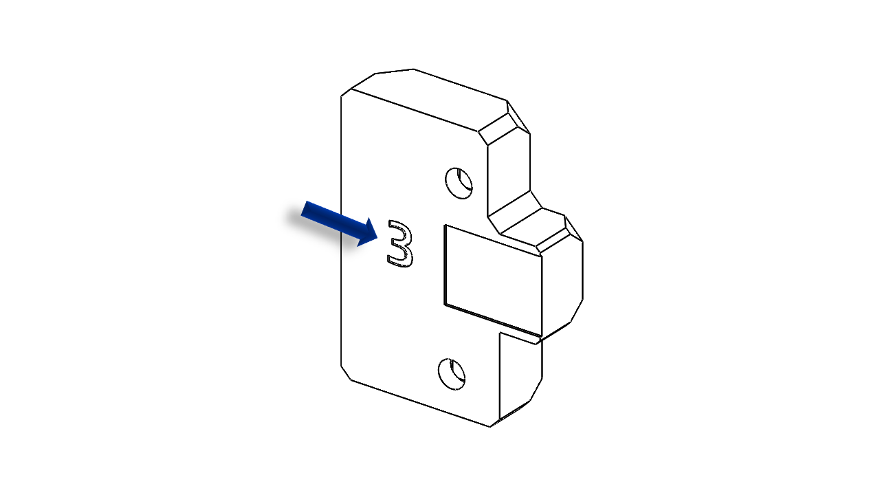
Next, we need these printed parts labeled with 2/3
 .
.
 .
.
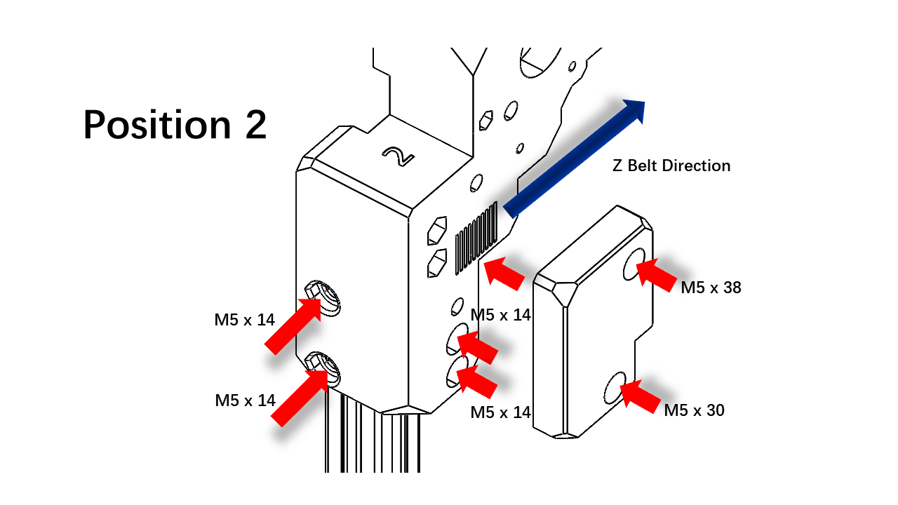
- Clip the Z belt to the bottom of Part 2. Note that the Z belt must match all slots on the parts. Use M5 x 14 to fix the bottom Z belt clip and the profile. Insert the M5 x 38 screw for later use.
 .
.
-
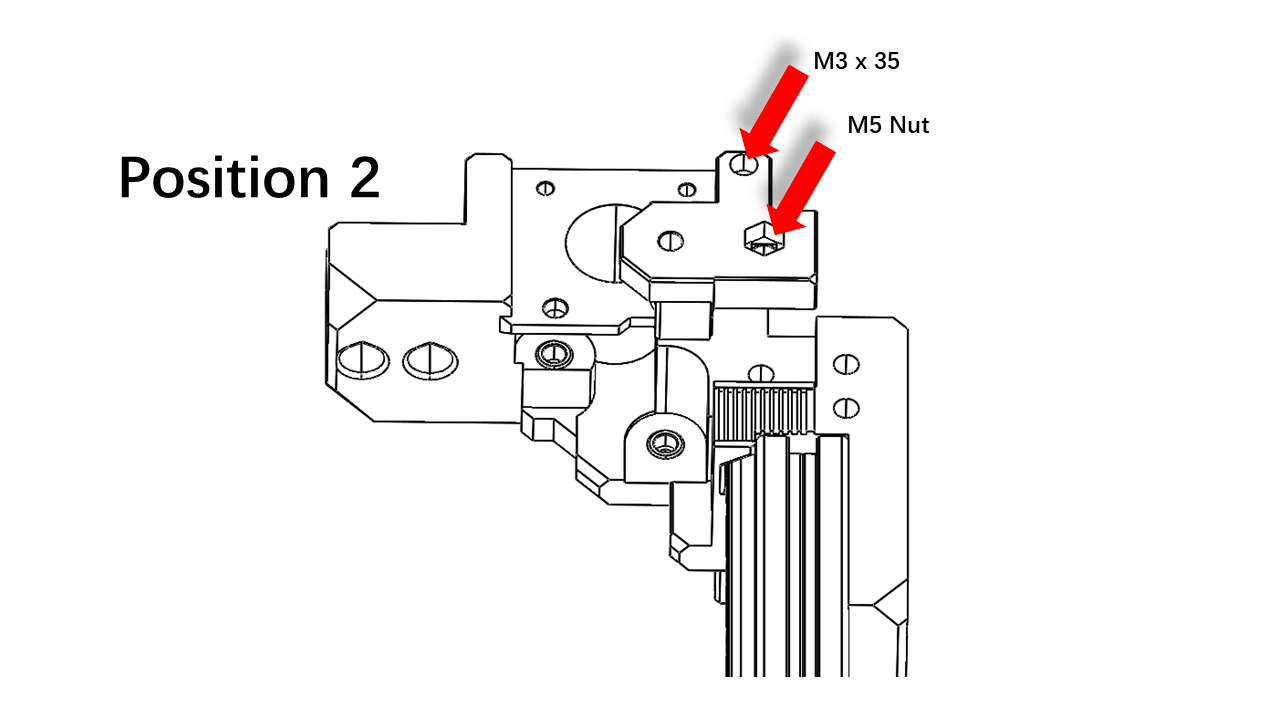
Use M3 x 35 to fix the printed part. Use M5 x 45 in the previous step to fix the pulley mount.
 .
. -
Use M5 x 14 and M5 x 30 to fix the belt clip and profile. Note that the Z belt must match all slots on the parts.
 .
.
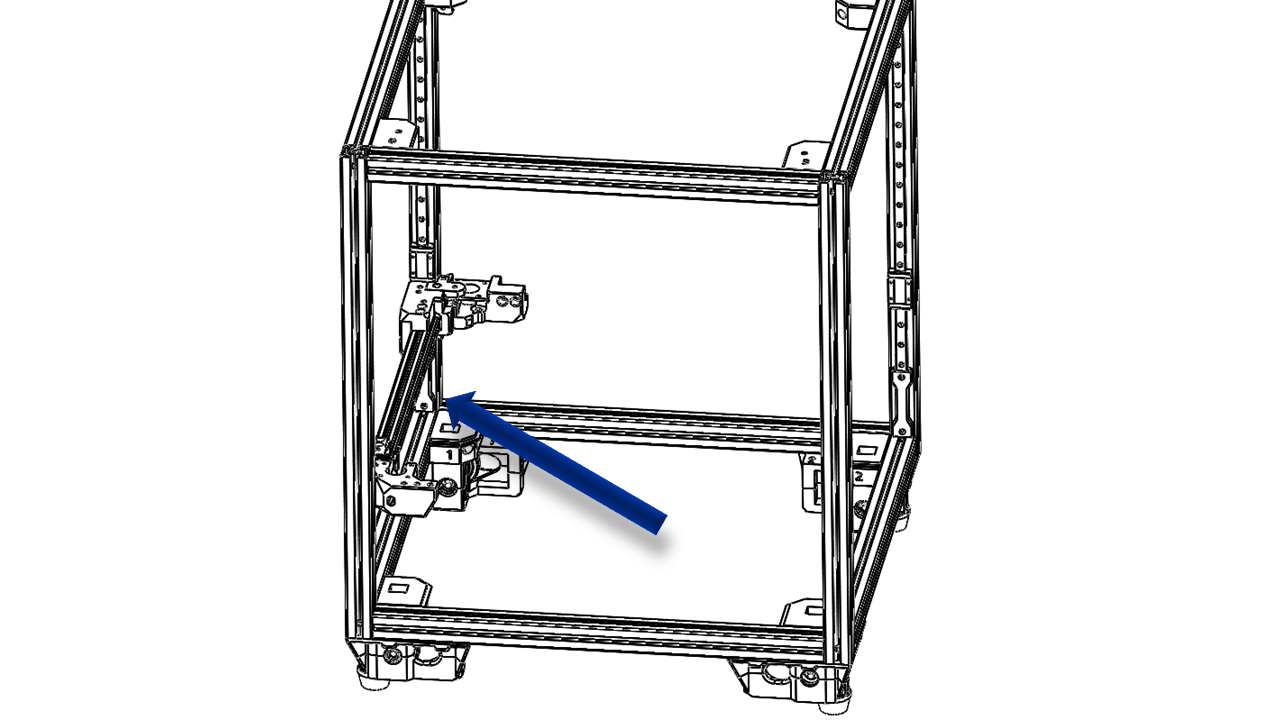
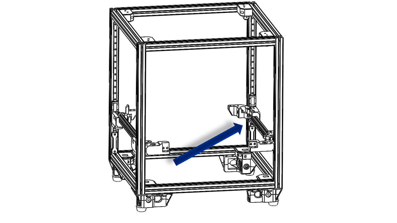
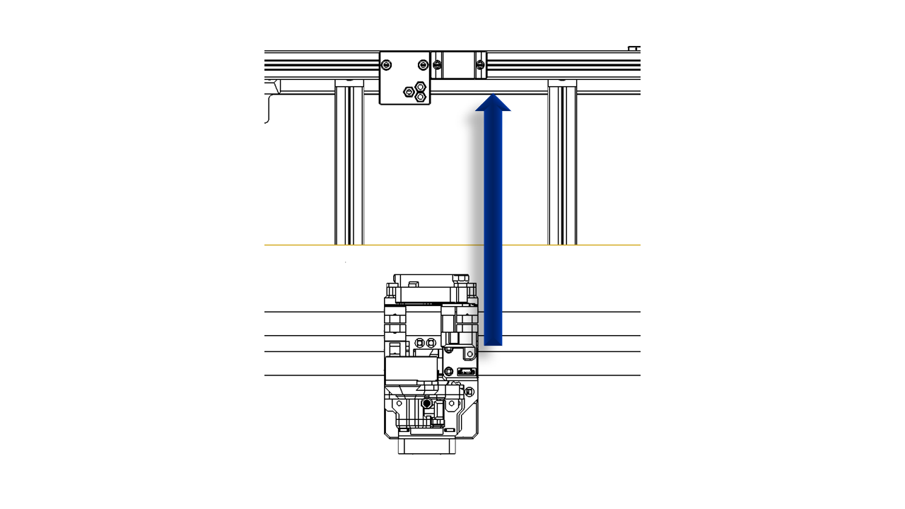
3.1.6 Install the gantry part
- As we finished the left and right parts of the gantry, it's now time to put them on the frame.
- Put them into the frame and pass the Z-belt through the Z drive as shown.
 .
.
 .
.
-
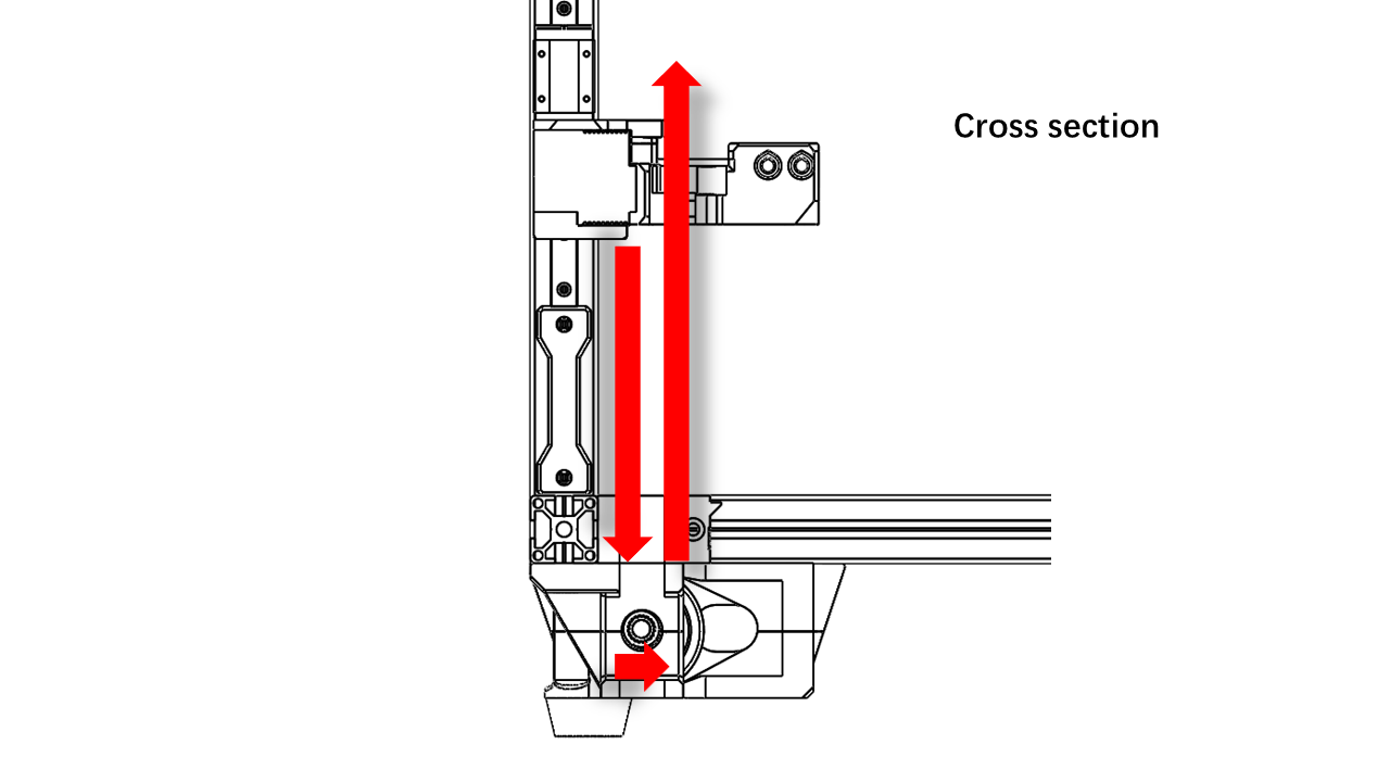
Pass the Z-belt as shown. Do this for all Z belts.
 .
. -
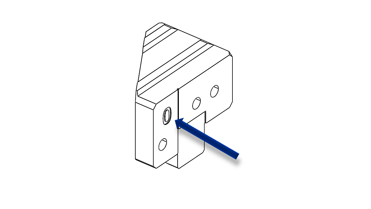
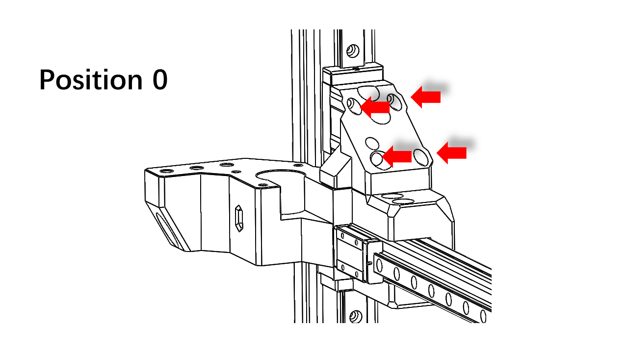
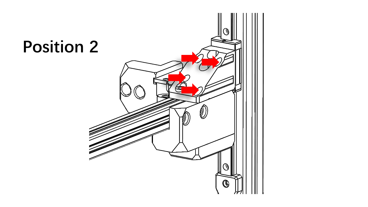
Now take the Z rail mount for part 0. Note that the rail mount has a label on it. The labels must match.
 .
. -
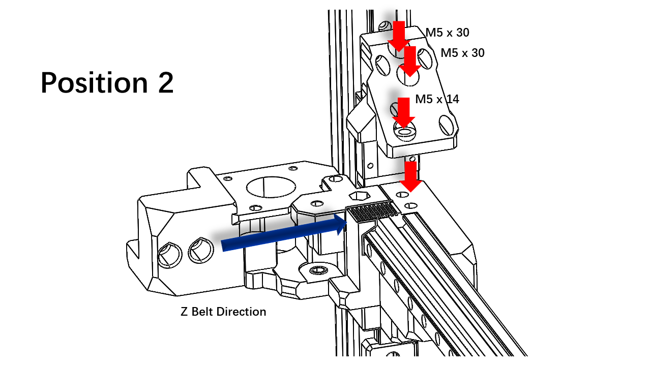
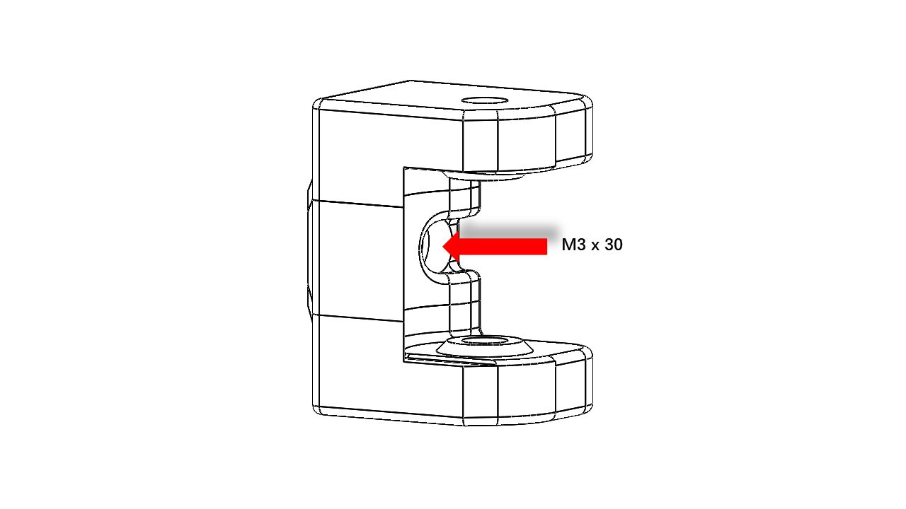
Clip the Z-belt with the rail mount as shown, use M5 x 30 and M5 x 14 screw to tighten. The belt must match all slots on the gantry part. Once you are done, pull the belt to see if it's aligned.
 .
. -
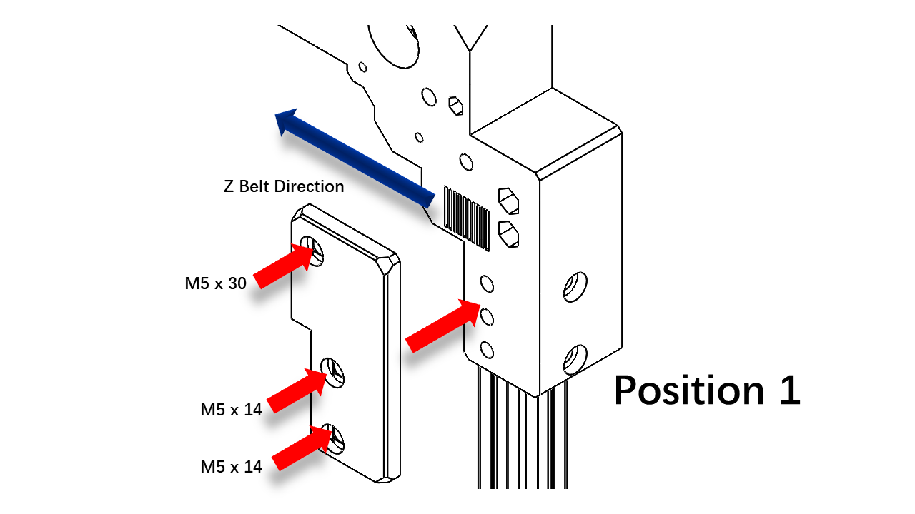
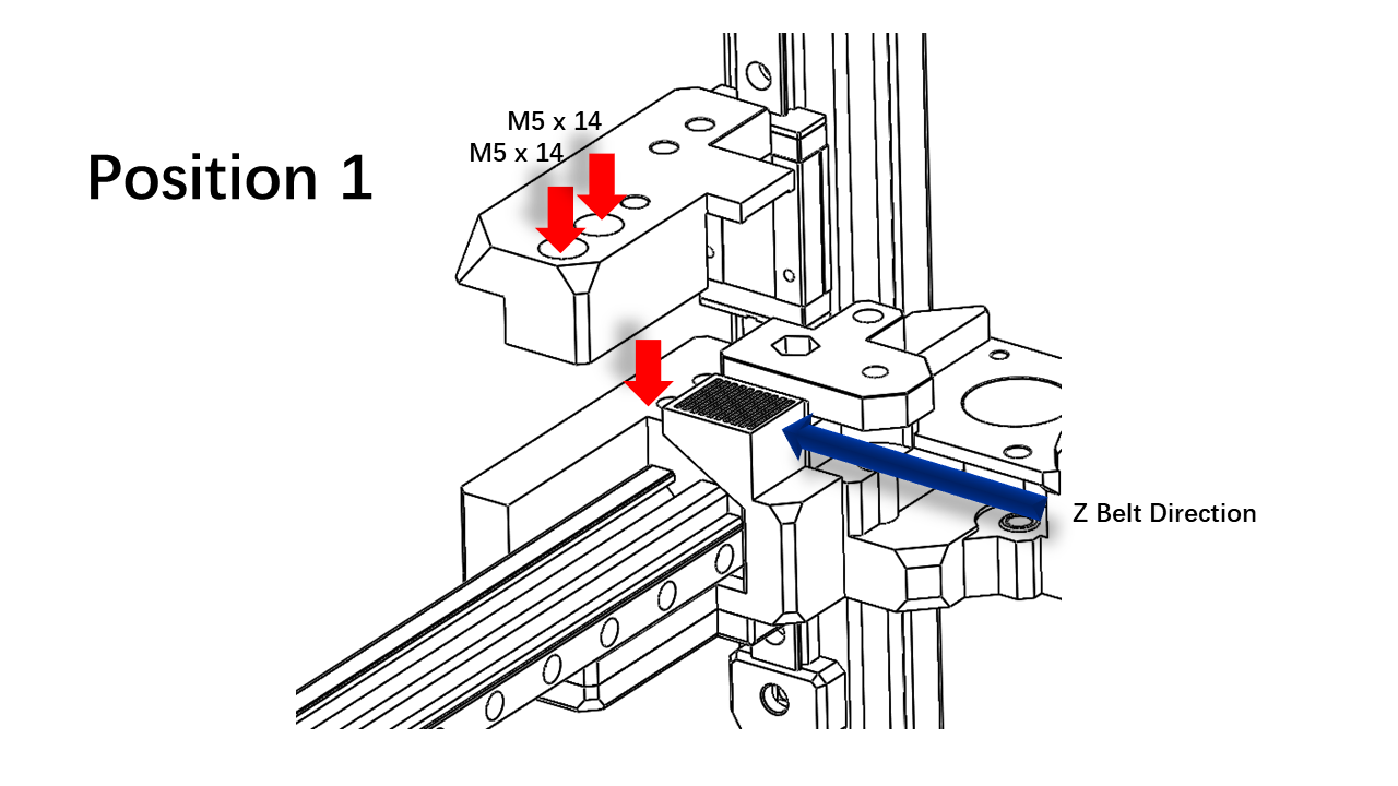
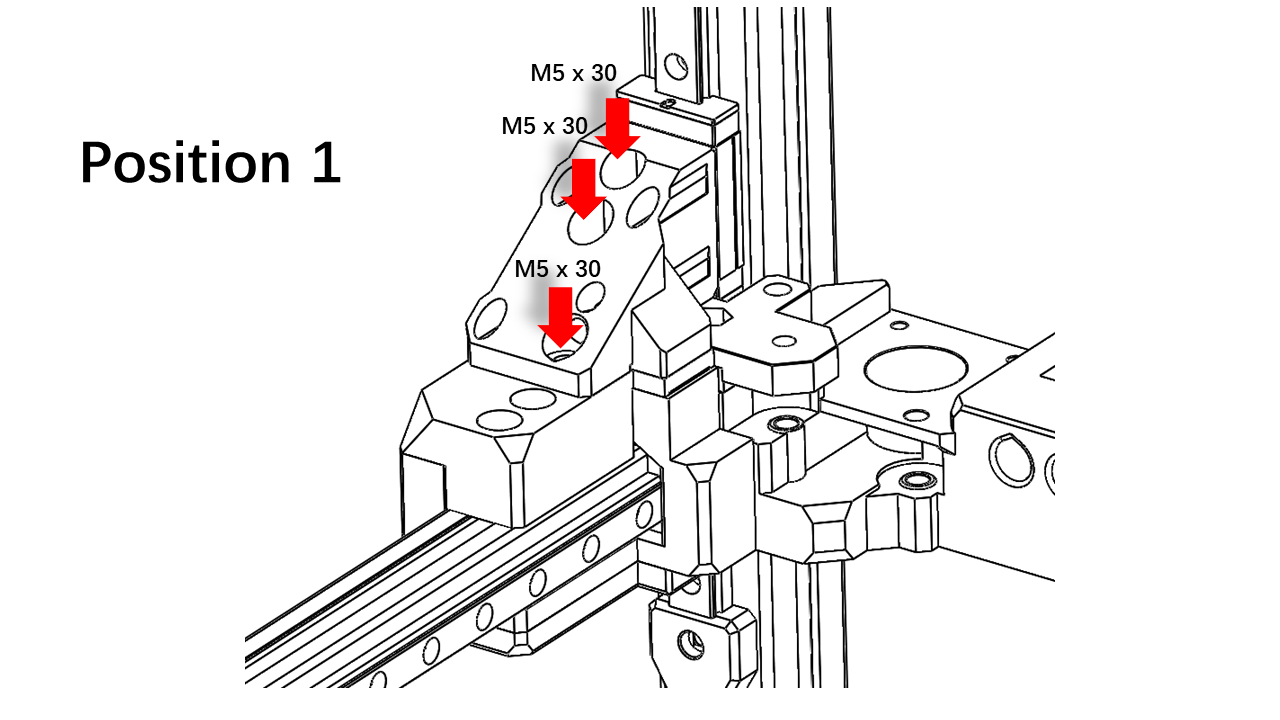
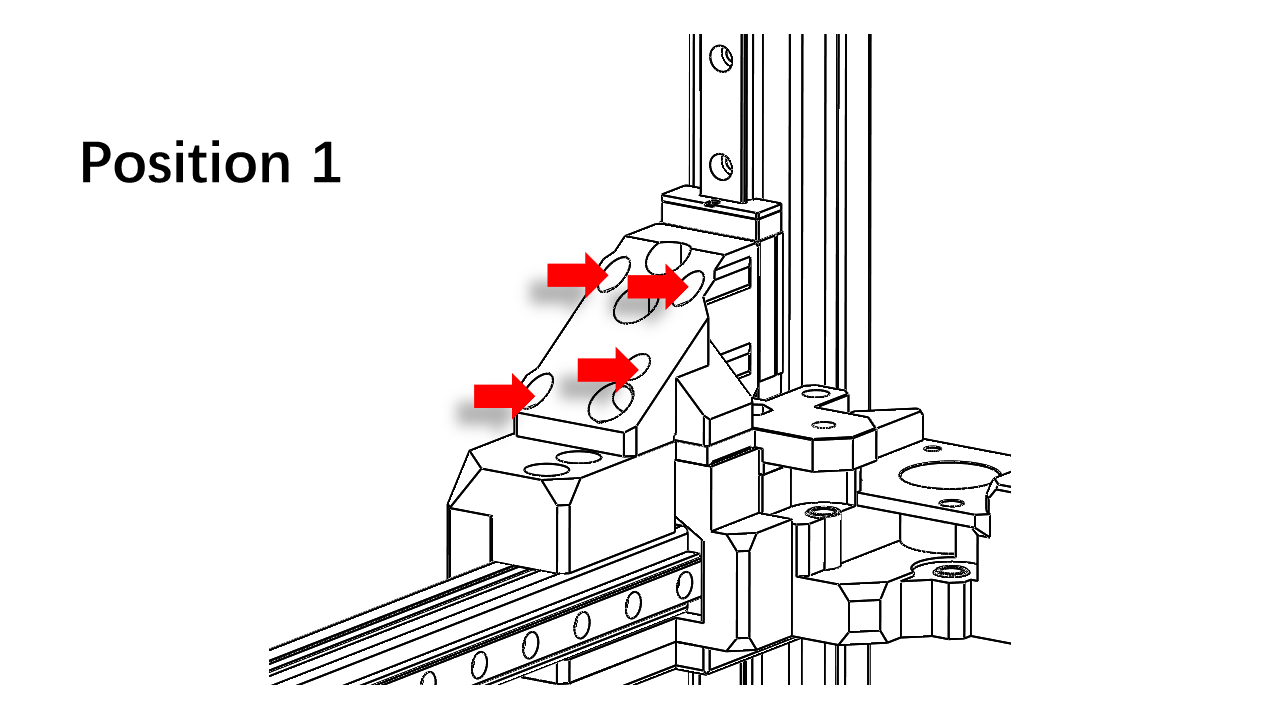
For position 1, we need to first install the Z belt clip as shown.
 .
.
- The rest is similar to the previous part. Note that the rail mount has a label on it. The labels must match.
 .
.
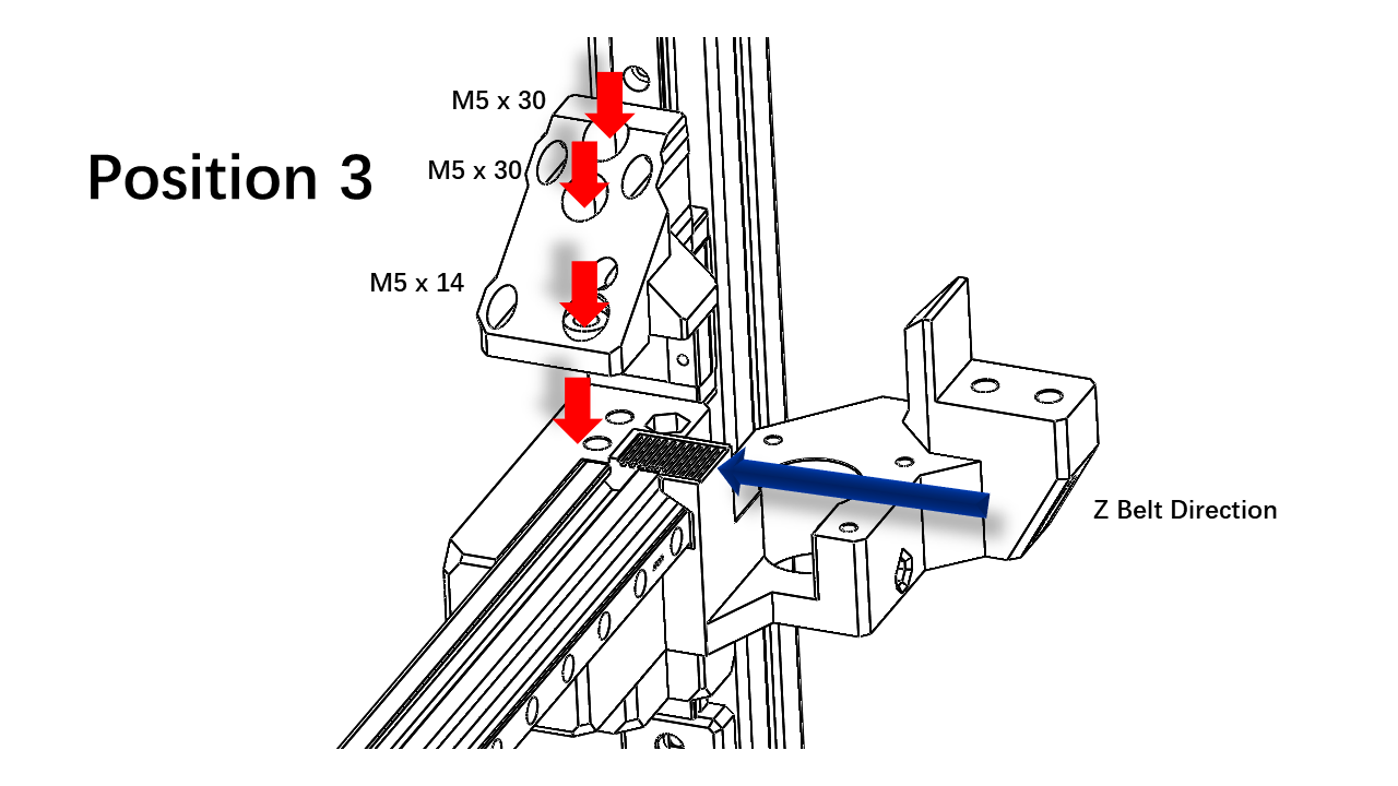
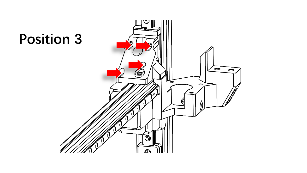
- Now take the Z rail mount for part 2. Note that the rail mount has a label on it. The labels must match.
- Clip the Z-belt with the rail mount as shown, use M5 x 30 and M5 x 14 screw to tighten. The belt must match all slots on the gantry part. Once you are done, pull the belt to see if it's aligned.
 .
.
- Perform the same procedure for Part 3
 .
.
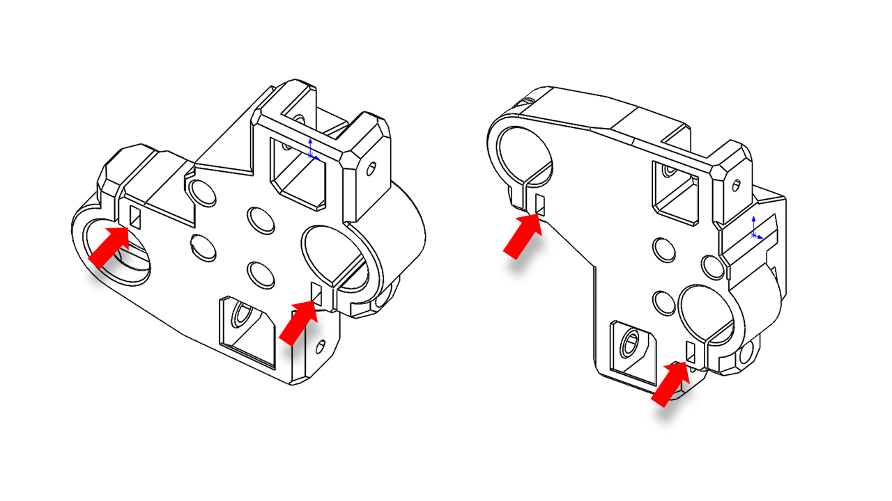
- Now install the rail mount on the rail sliding block using M3 x 14 screws.
 .
.
 .
.
 .
.
 .
.
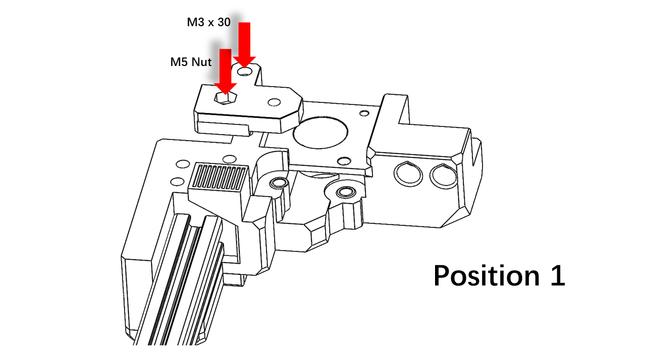
- Pre insert an M3 x 25 screw here.
 .
.
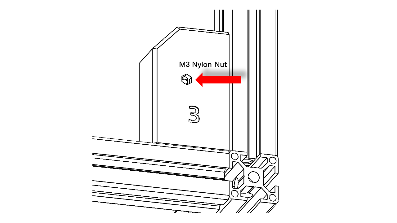
- Insert an M3 nylon-locked nut here.
 .
.
- Insert the pulley base, and slightly screw in the metal part of the nylon-locked nut.
 .
.
- Pass the Z-belt to the pulley base as shown, use an M5 x 35 screw as the shaft.
 .
.
- Insert the hex tool into the holes to guide the pulley and pass the Z belt as shown. Pull out the hex tool and tighten the screw.
 .
.
- Repeat these steps for all four pulley bases
3.1.7 Install the 375mm profile
- Now take the shortest 2020 for the gantry. Pre-insert the spring nut and square nut as listed.
 .
.
- Insert the 375mm profile here as shown.
 .
.
- Use an M5 x 14 screw to tighten it.
 .
.
 .
.
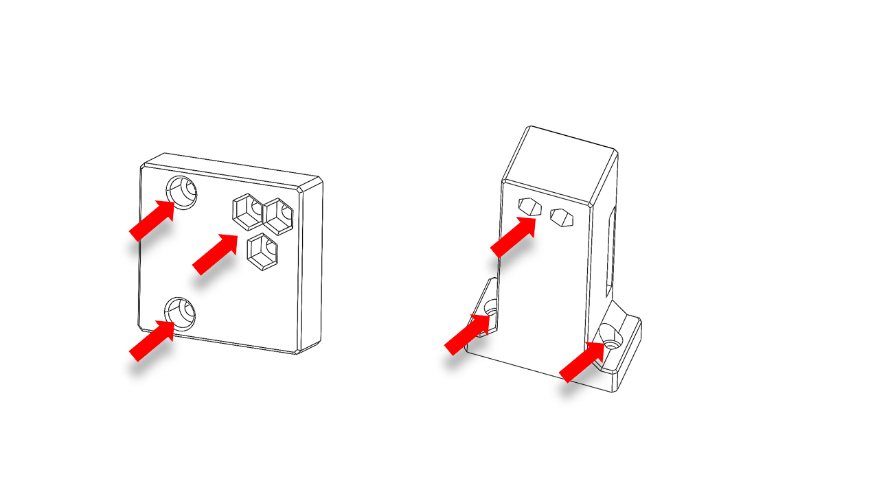
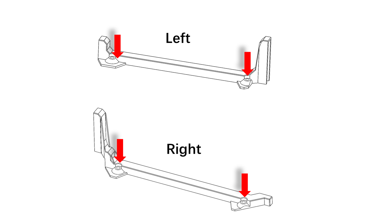
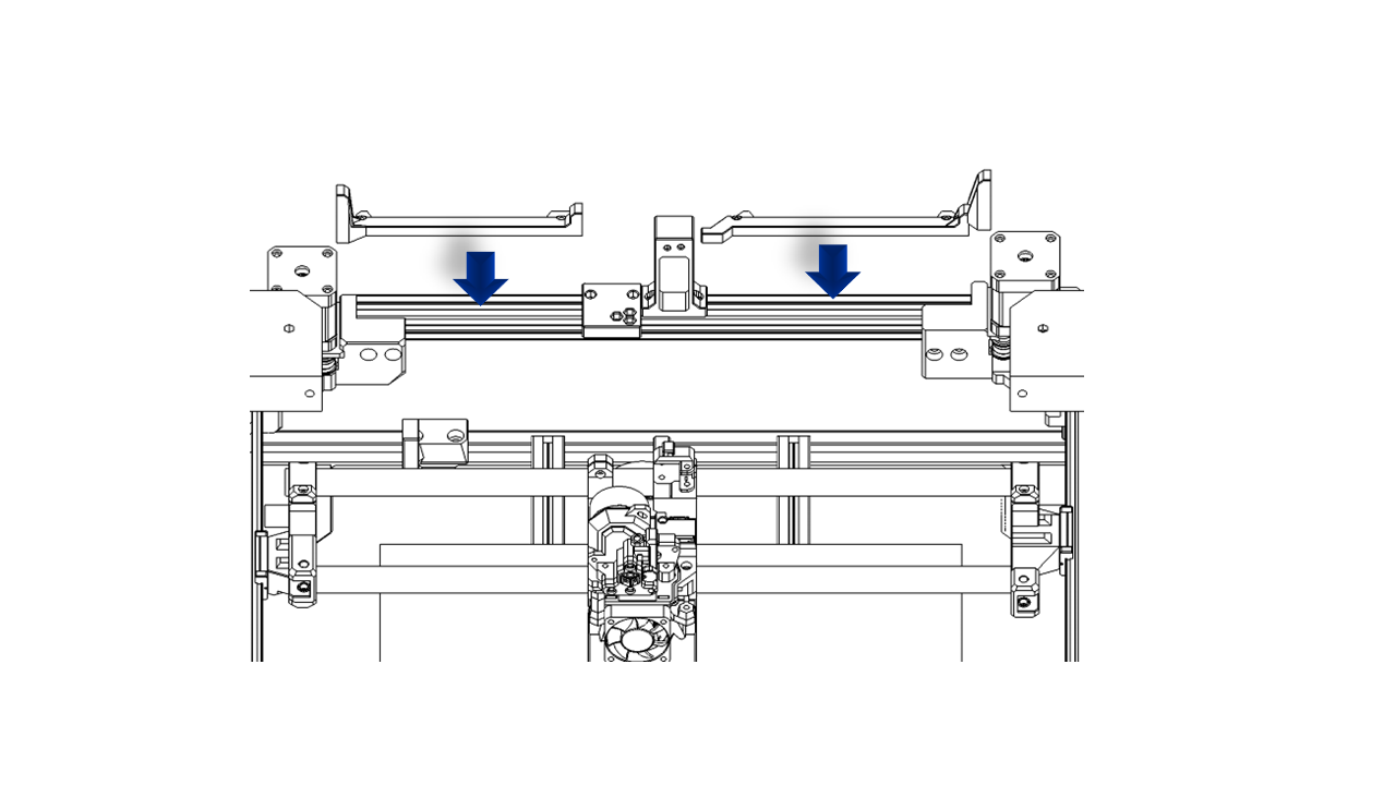
3.1.8 Install the Rod mount.
- Pre-insert the nut on the rod mount as shown.
 .
.
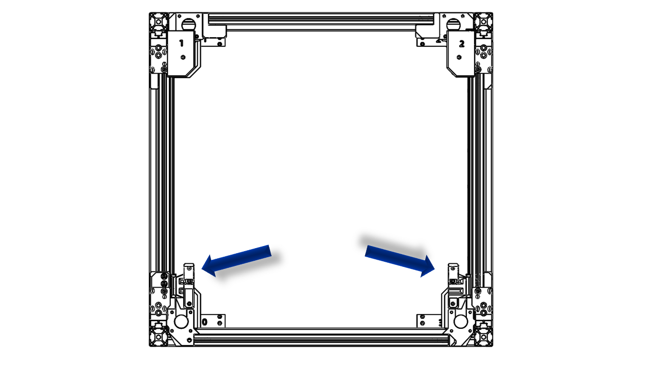
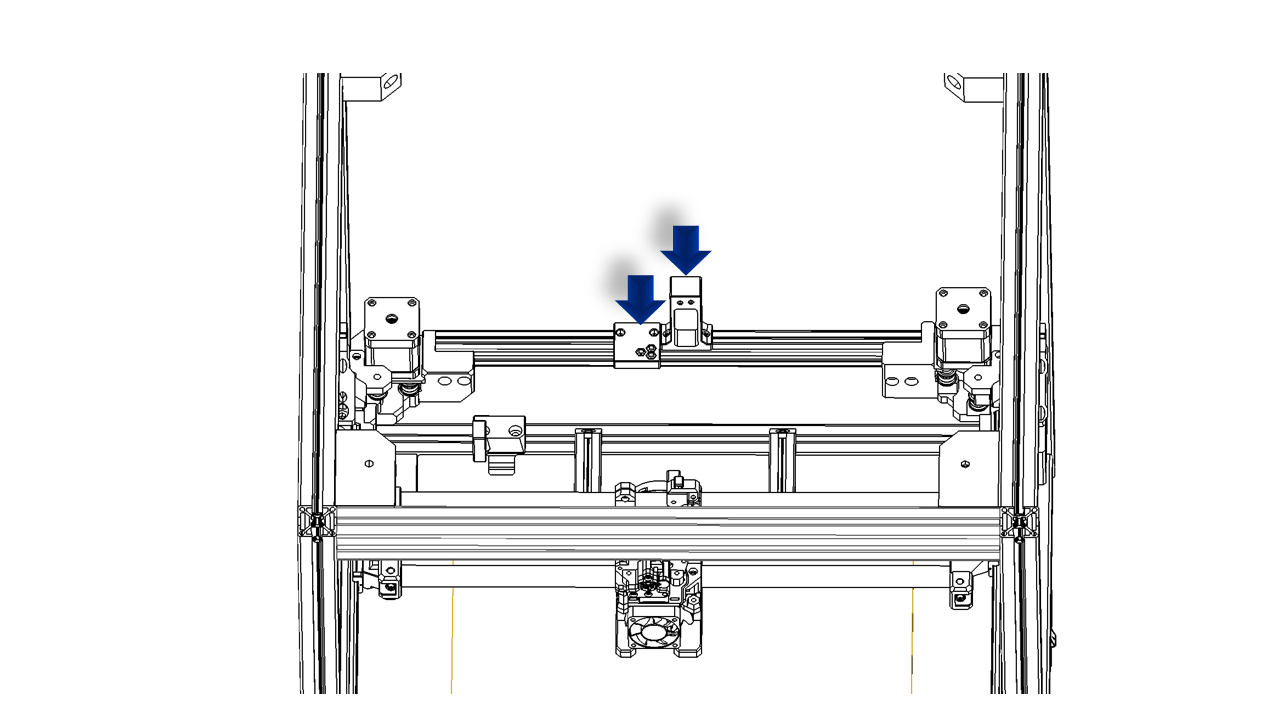
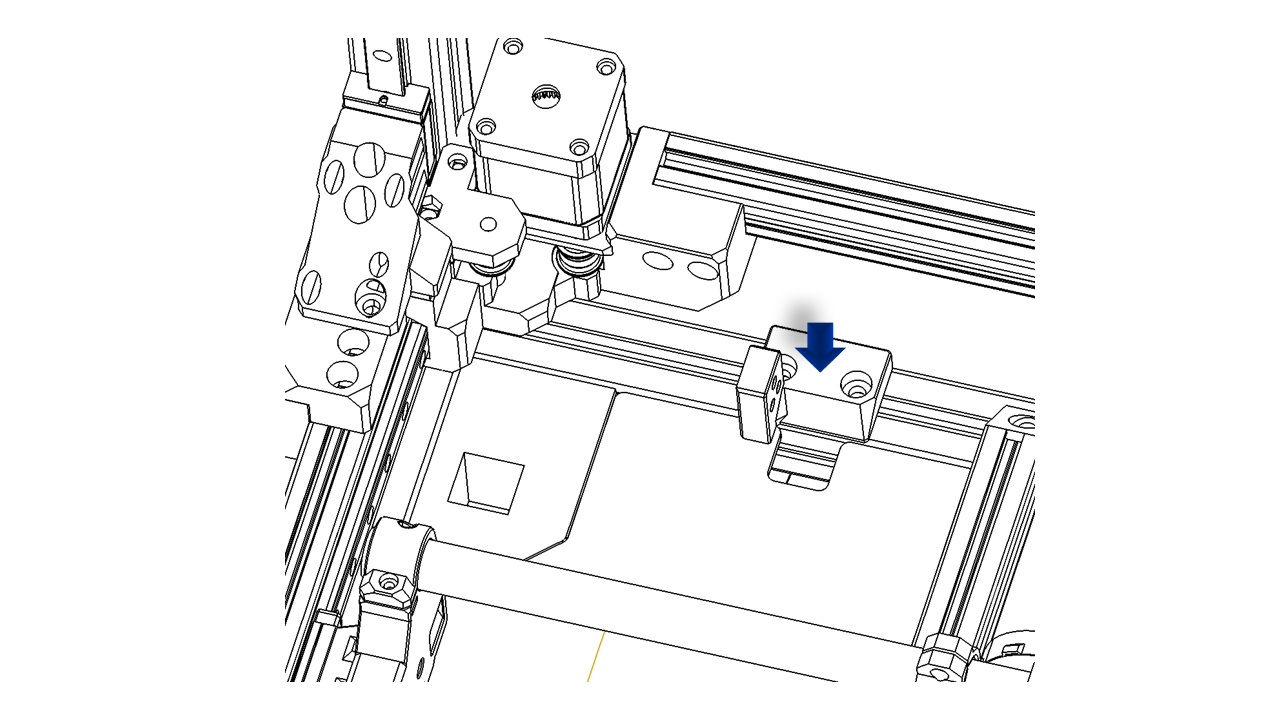
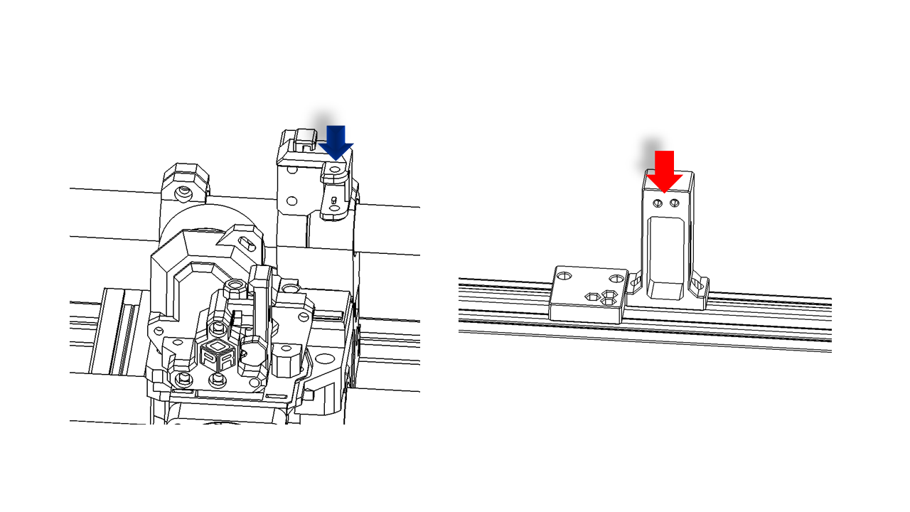
- Take off the rubber block on the Y rail. Slice them to the back and install the two rod mounts as shown.
 .
.
 .
.
 .
.
 .
.
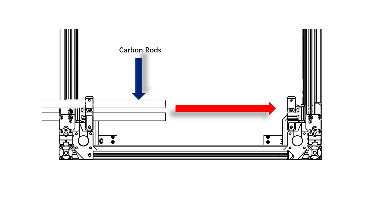
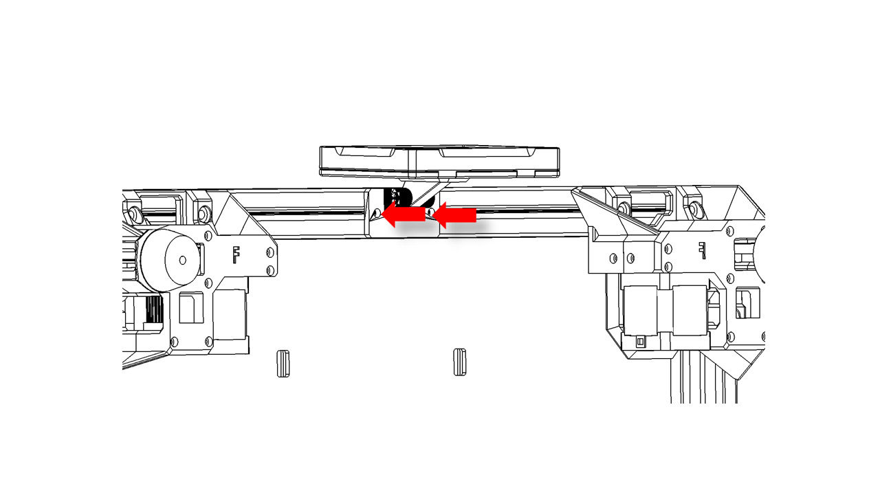
- Insert the two carbon rods as shown. Tighten the screws. Slide them to the front. If you feel too much friction. Untighten the screws on the 0/3 rail mount to release the stress in the system. Then tighten them. Slide the rods again, and you should feel no friction.
 .
.
 .
.
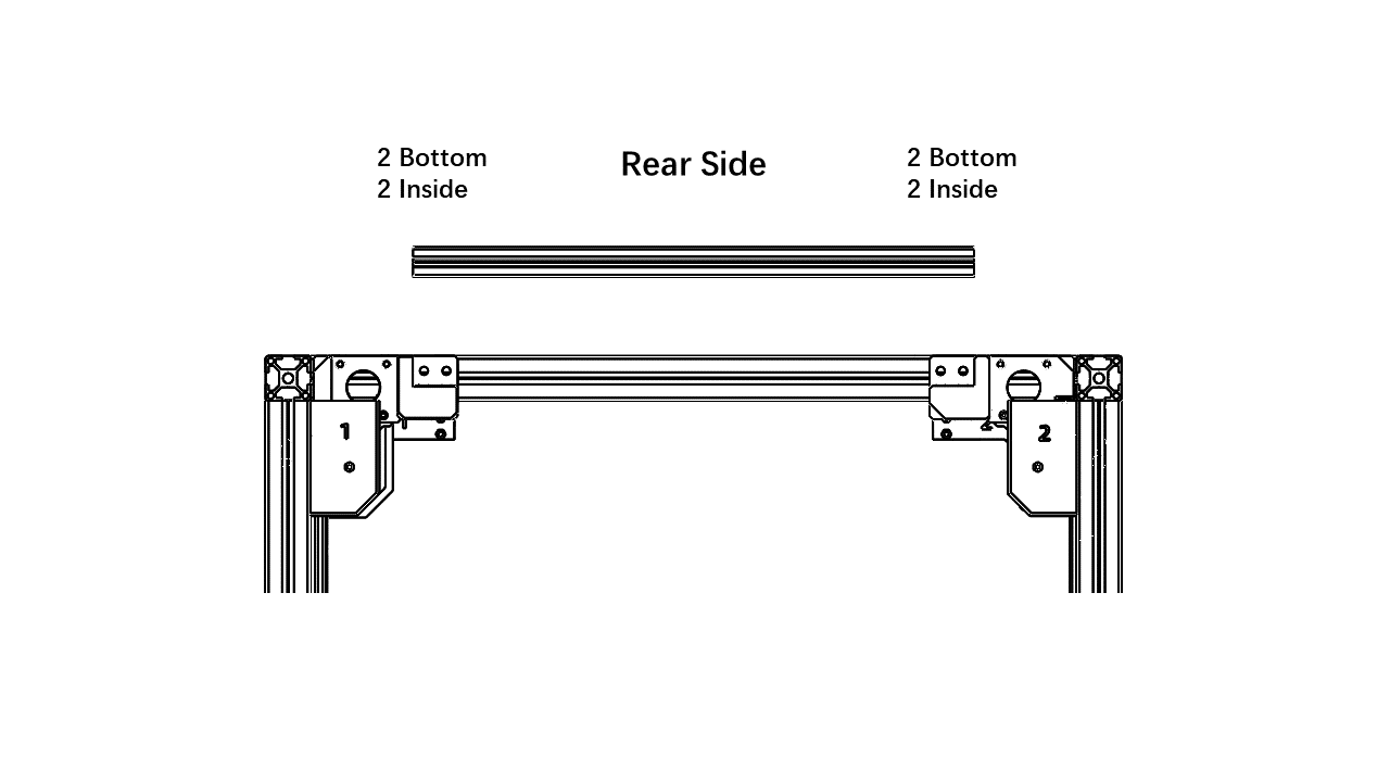
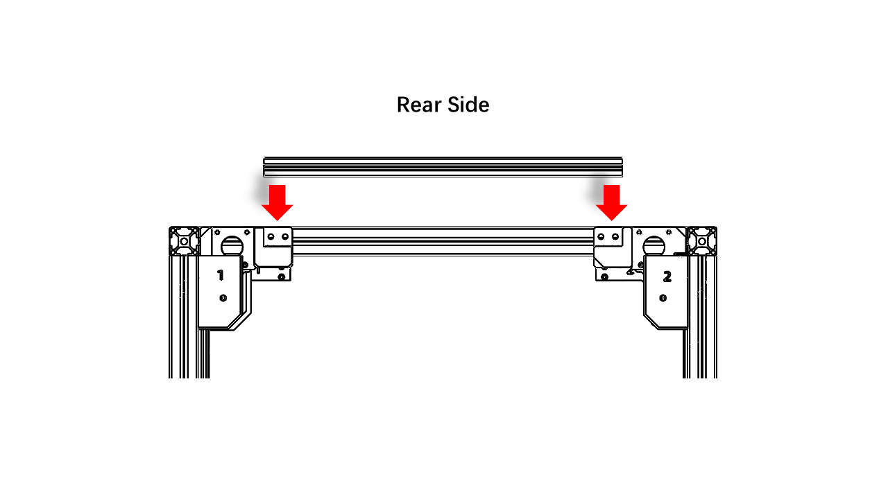
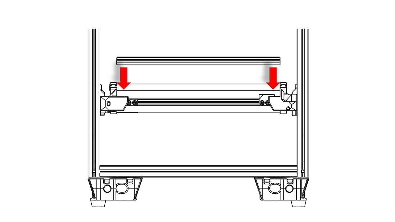
3.1.9 Install the front beam.
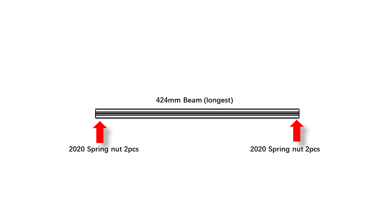
- Take the 424mm profile, which is the longest, pre insert all nuts as shown.
 .
.
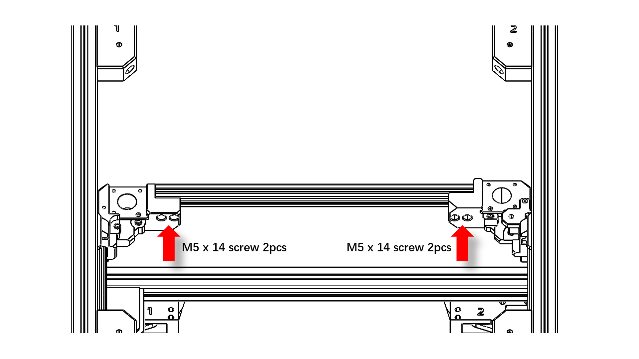
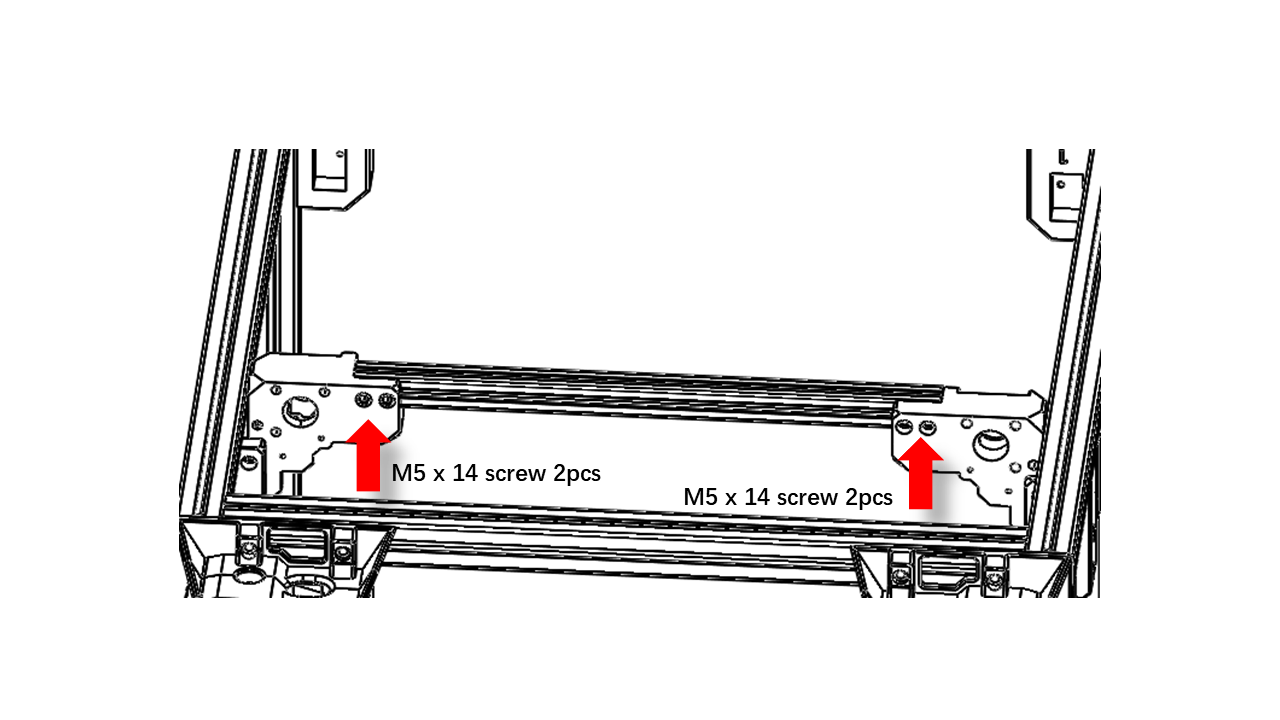
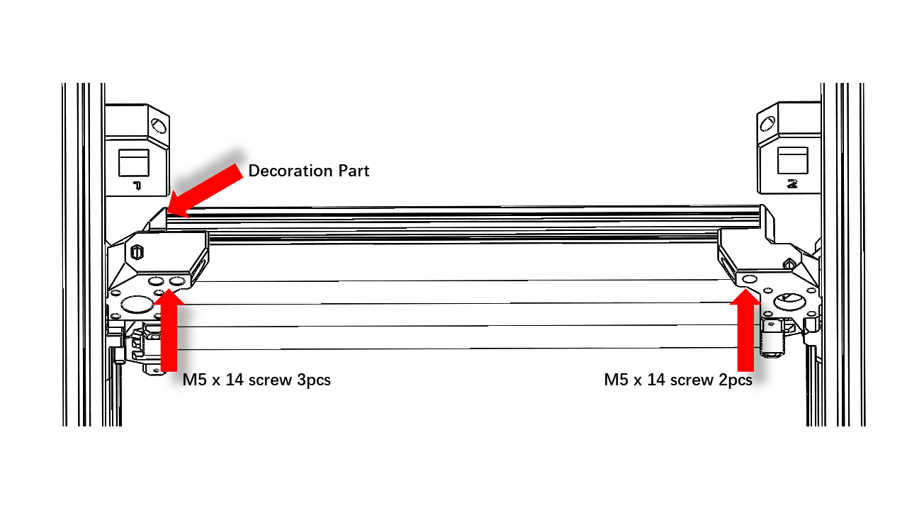
- Install the front beam with M5 screws as shown.
 .
.
- Note that there is one decoration part.
 .
.
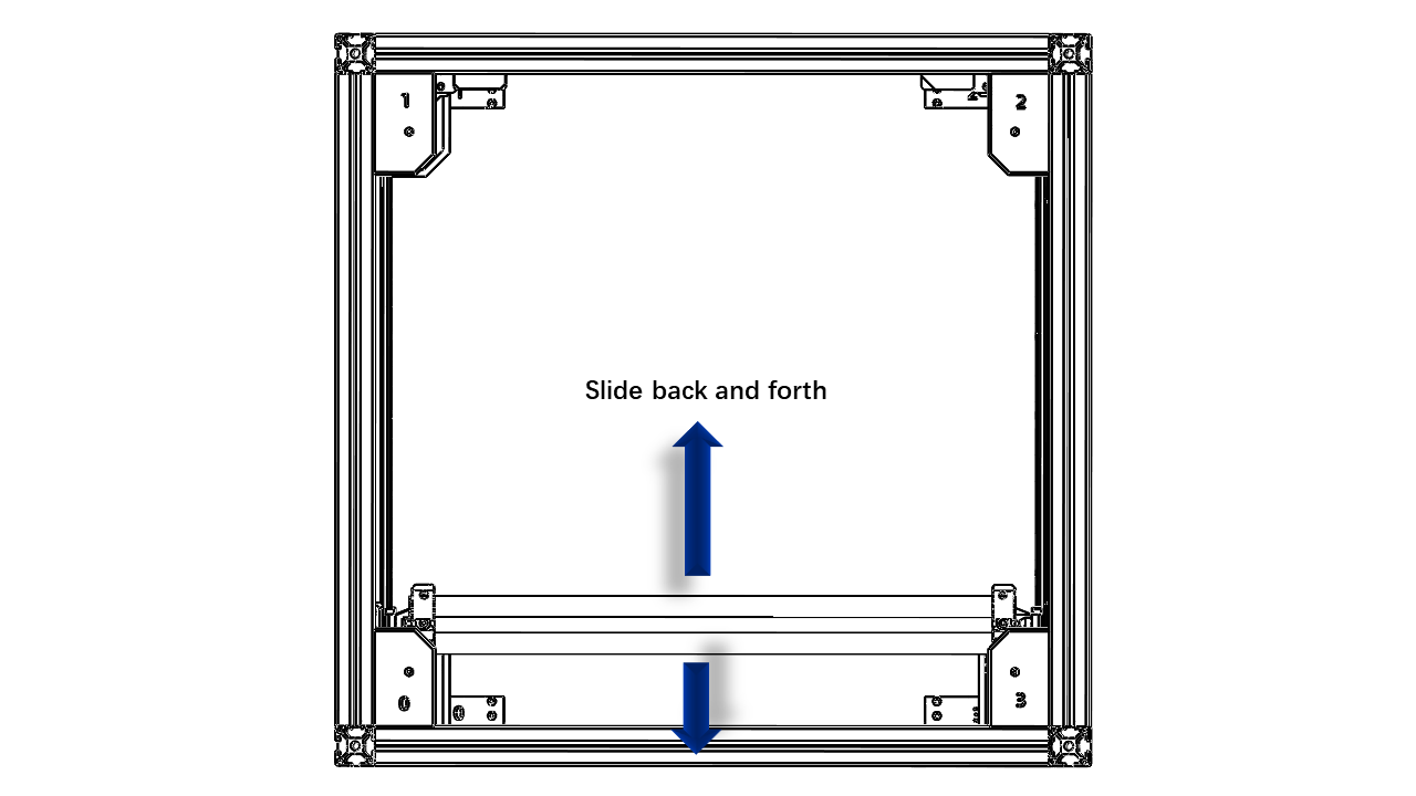
- Slide the Y axis back and forth to make sure there is no extra friction. If there is, release the M5 x 14 on the front beam, slide the Y axis to the very front, and tighten the front beam.
 .
.
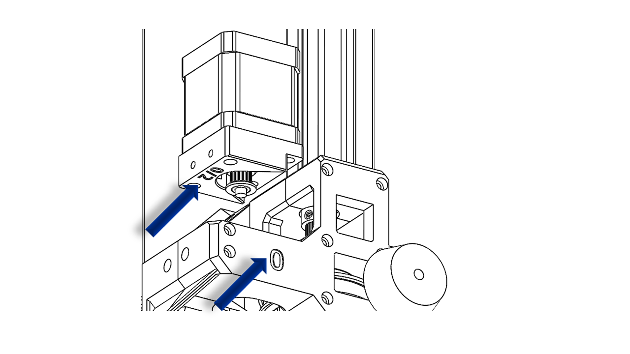
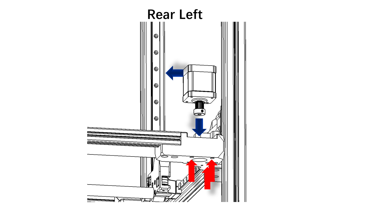
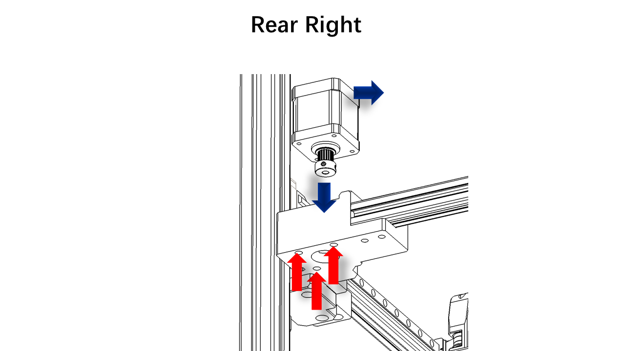
3.1.10 Install Z motors.
- Now we can install the Z motors. Insert the motors as shown. Note that there are labels on the motor mount; you should make sure they match the positions you are operating.
 .
.
 .
.
- Now insert an M3 x 20 screw at these locations.
 .
.
- Fully tighten the screw to make sure the motor belt is reaching the ideal tension. There should be no gaps here.
4. Tool Head
4.1 Assemble
4.1.1 Hot end
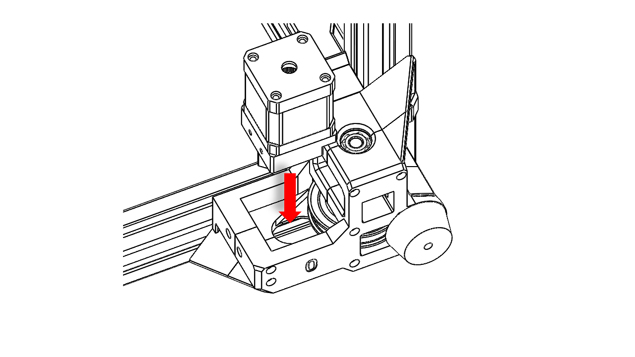
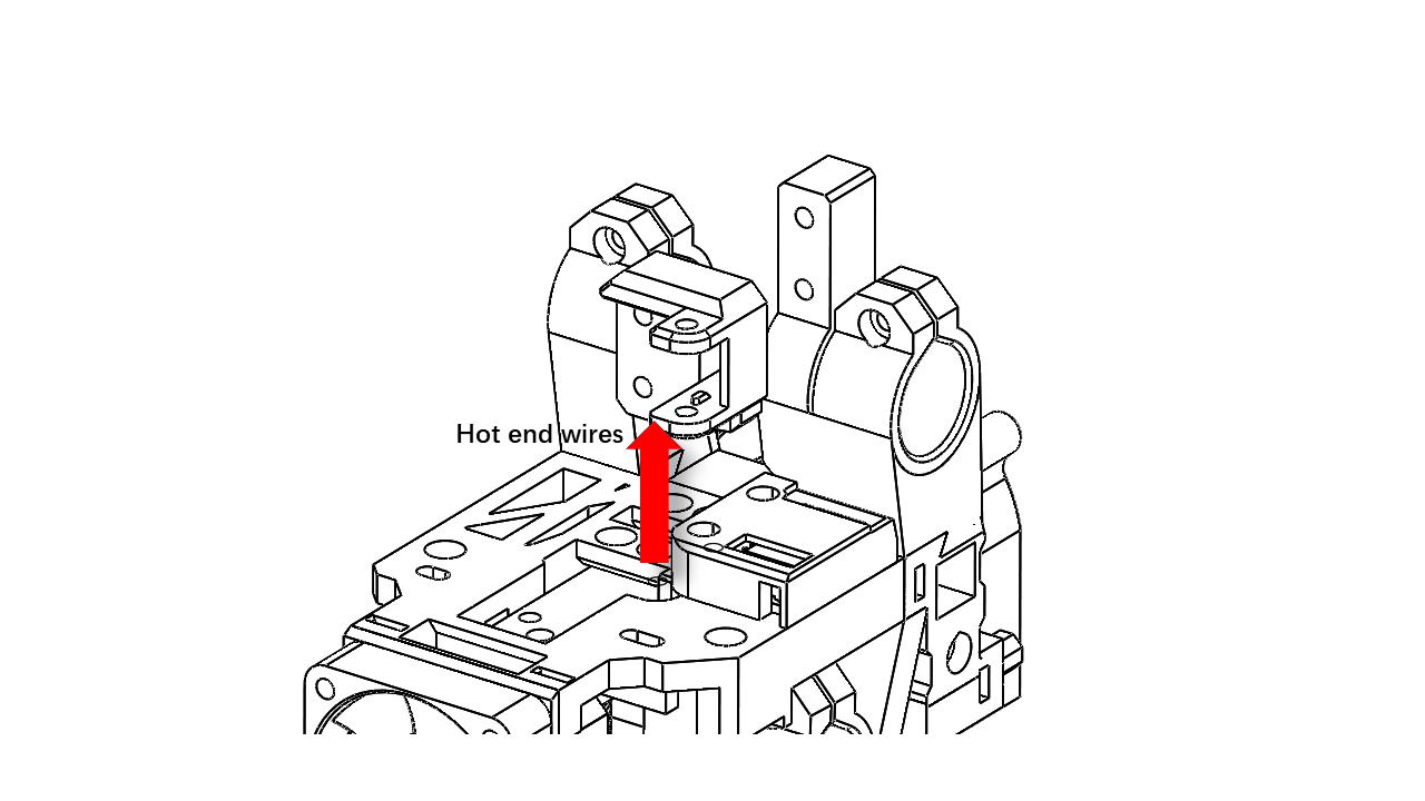
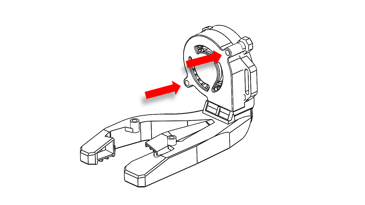
- Take the hot end module and install it from below. Note the orientation.
 .
.
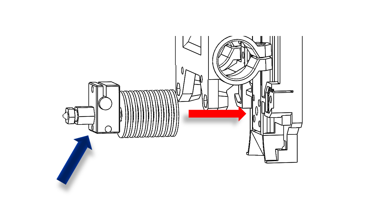
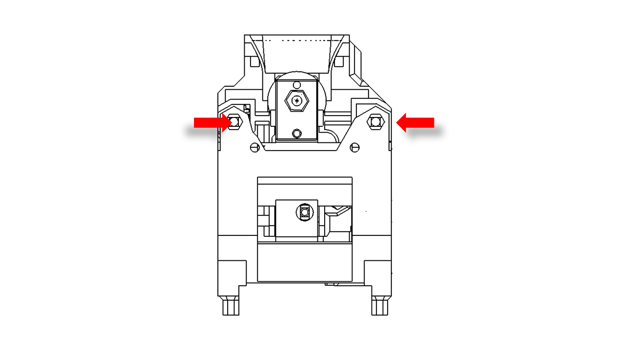
- The hot end is mounted with one pair of diagonally placed screws. For default V6 use M2.5x14. Make sure you tightened them properly.
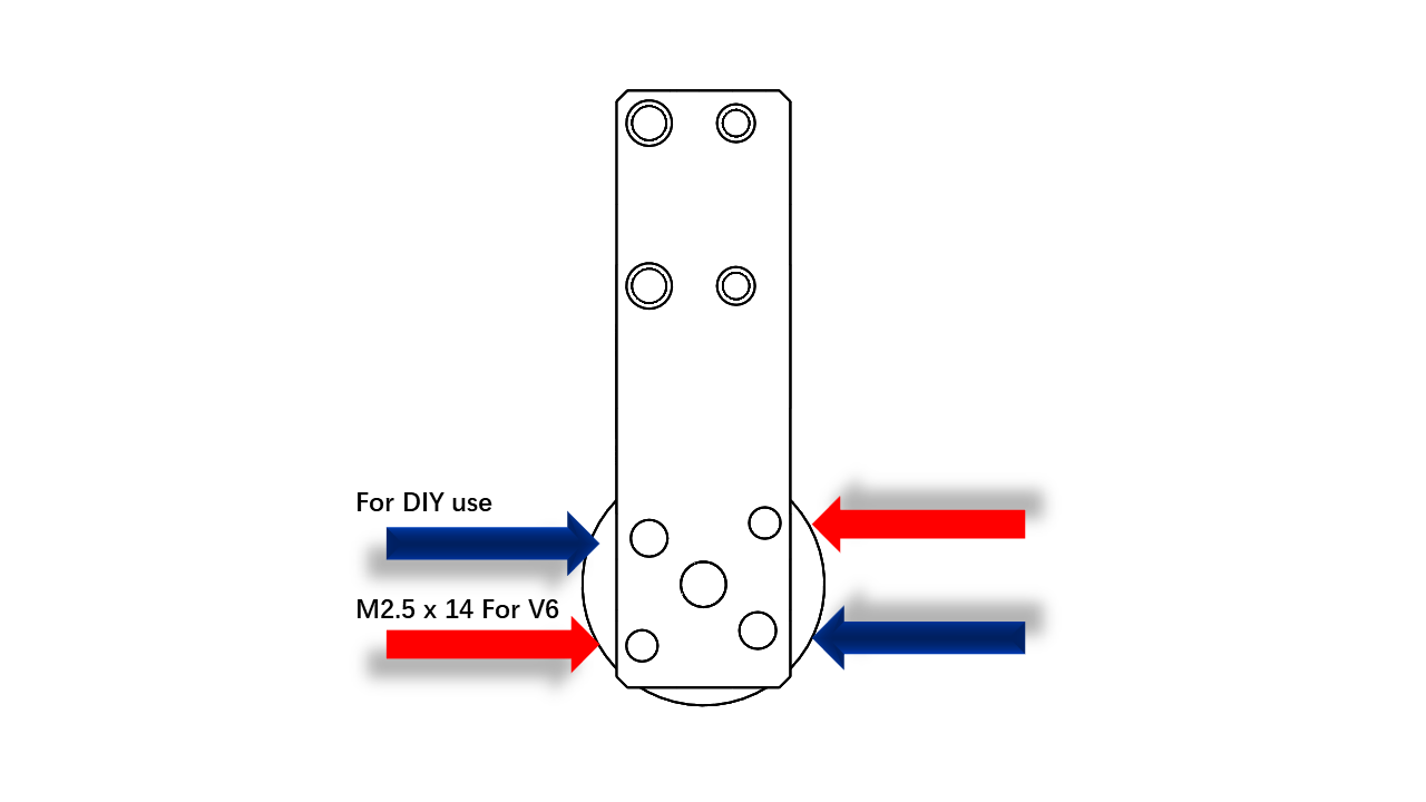 .
.
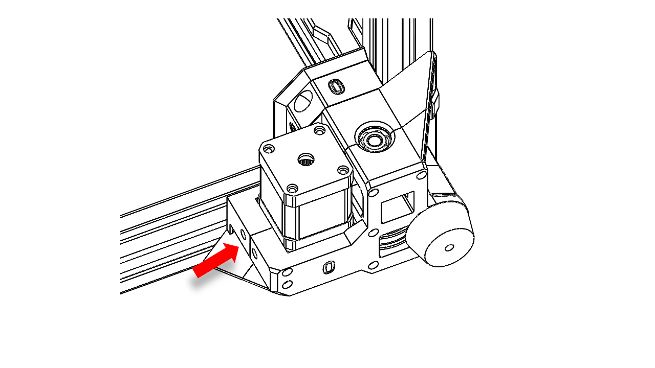
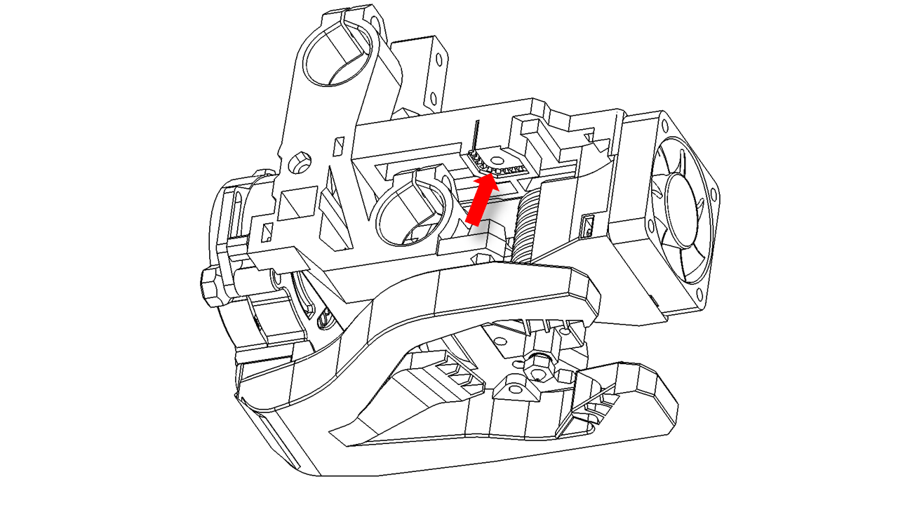
- The hot end wires should come out from the gap here.
 .
.
4.1.2 Prepare the Fans
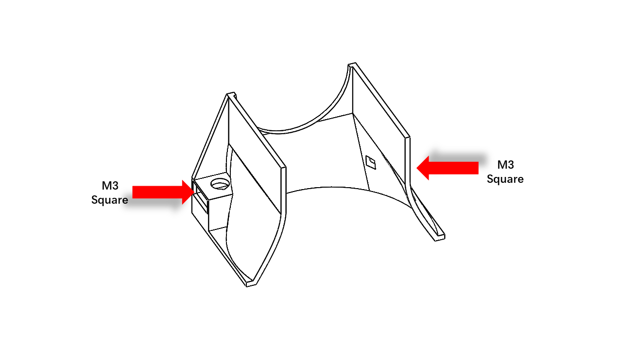
- First, we need to pre-insert nuts in the wind tunnels.
 .
.
 .
.
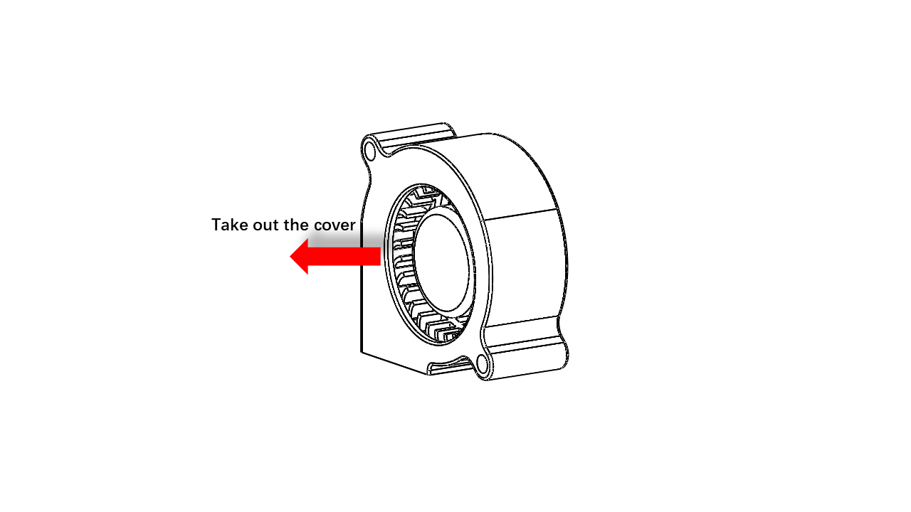
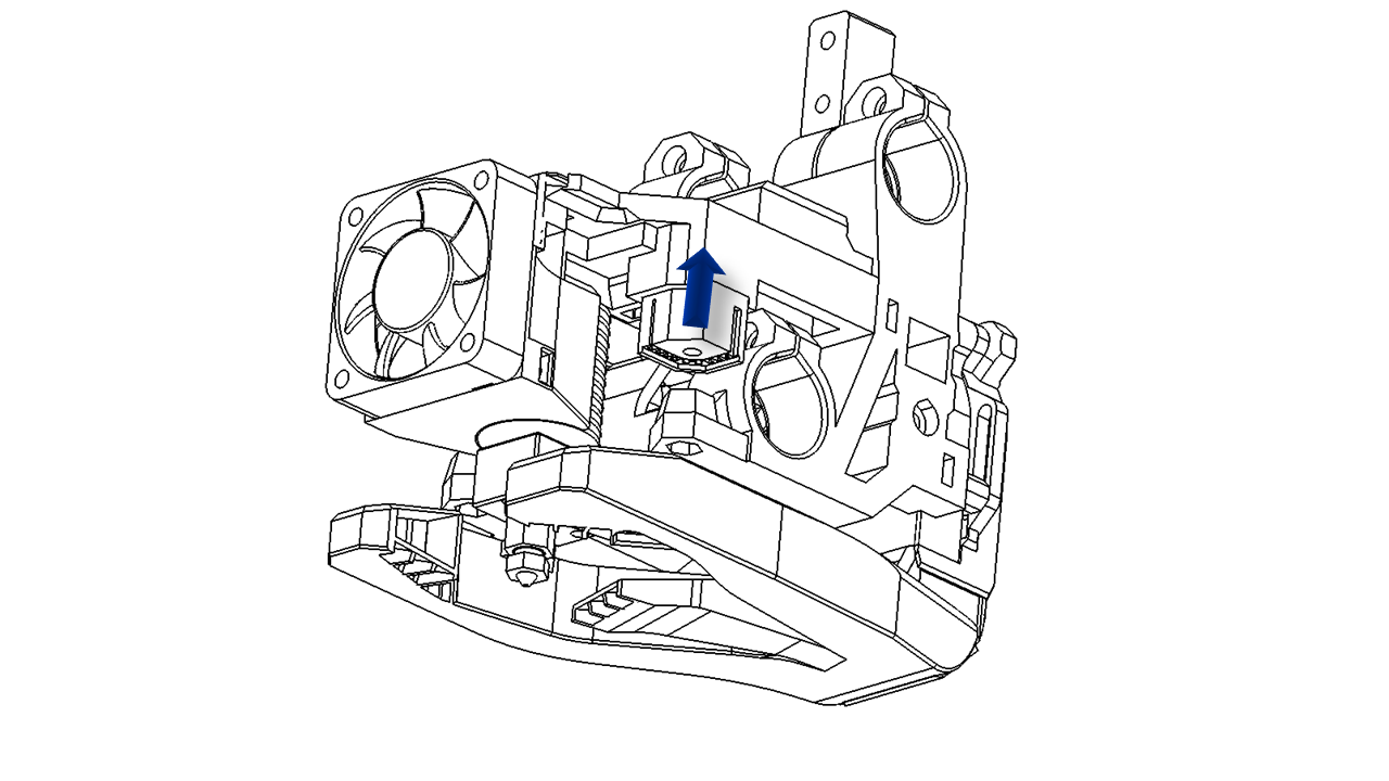
- Now we need to prepare the blower fan. Take out the 5050 fan cover. There are two clips on the fan. It should come off without too much trouble.
 .
.
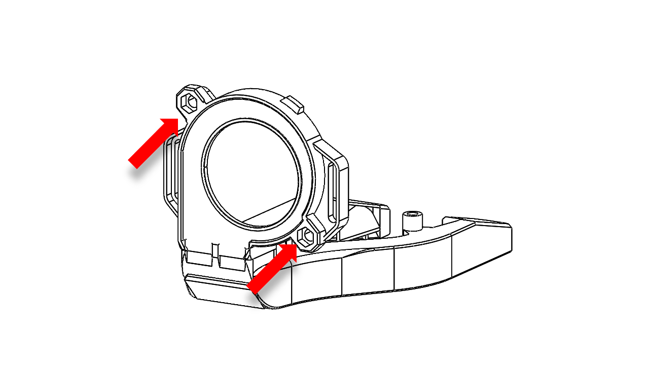
- Now insert the rest of the 5050 fan into the printed parts as shown.
 .
.
4.1.4 Prepare the belts
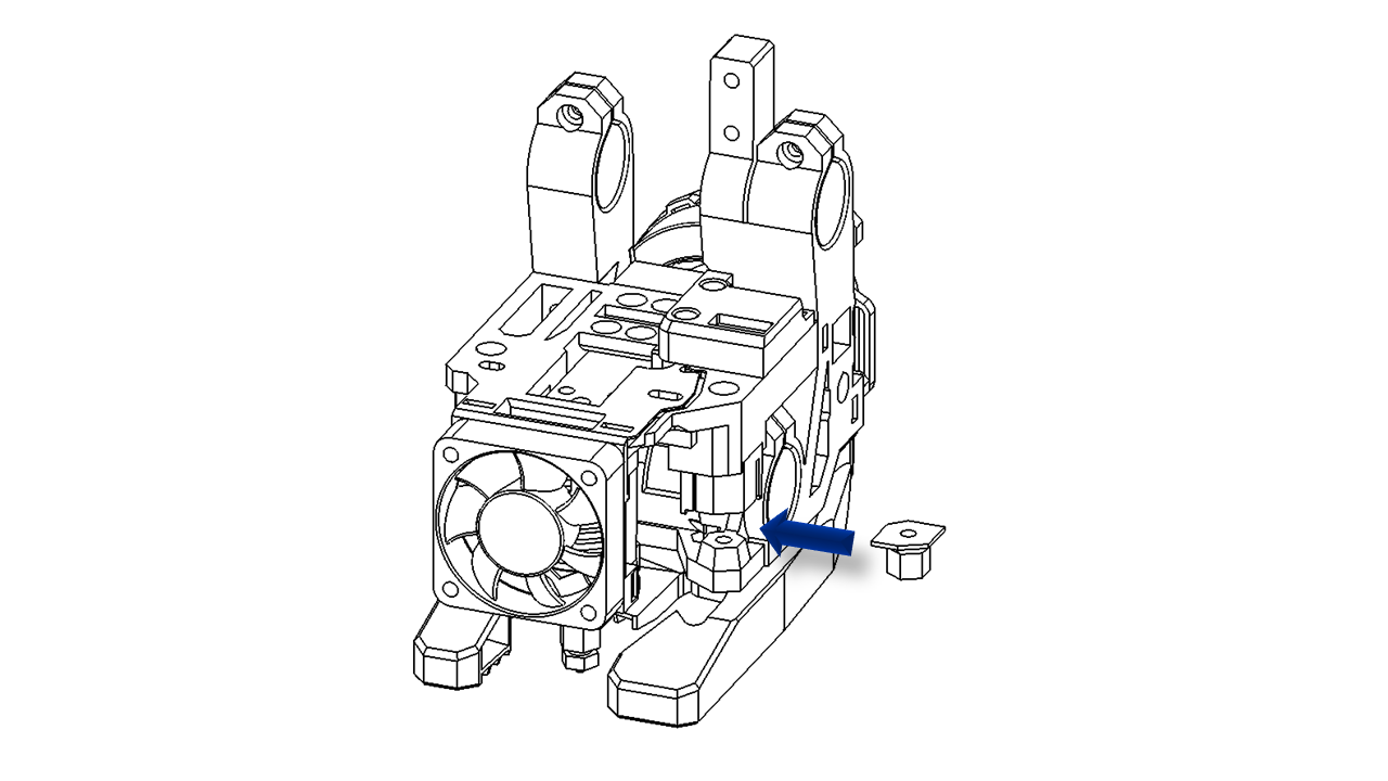
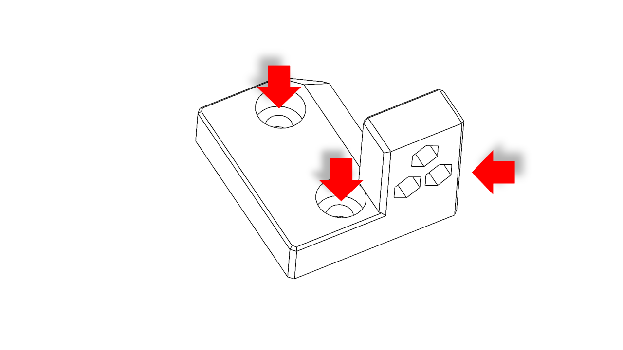
- Pre-insert the M3 nylon nut here before we install the fan.
 .
.
- Pre-insert the timing belt here.
 .
.
- Then slide in the left belt support as shown.
 .
.
- Tighten the structure using M3 x 45. The belt should point out as shown.
 .
.
.
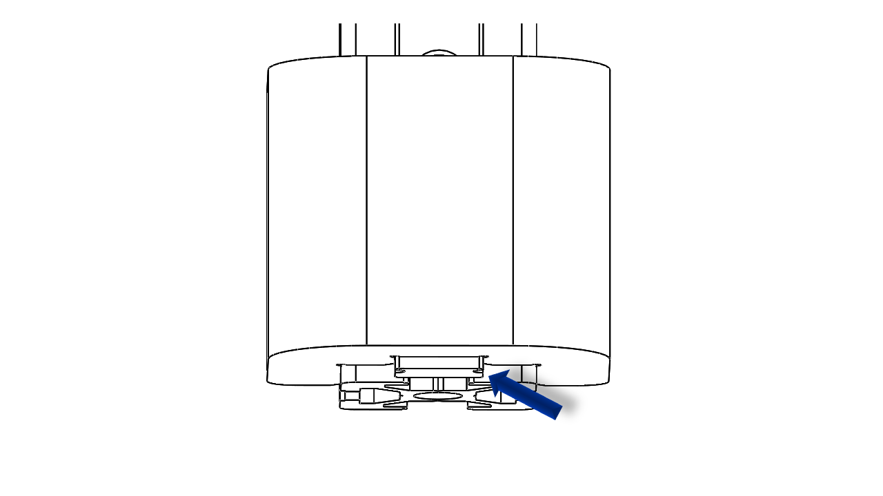
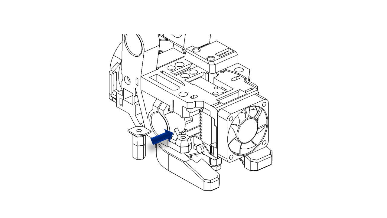
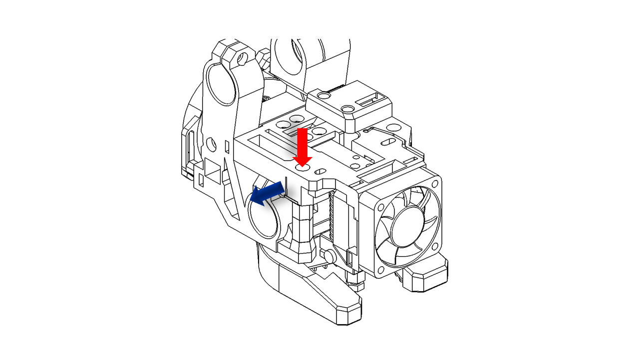
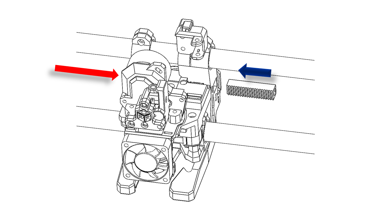
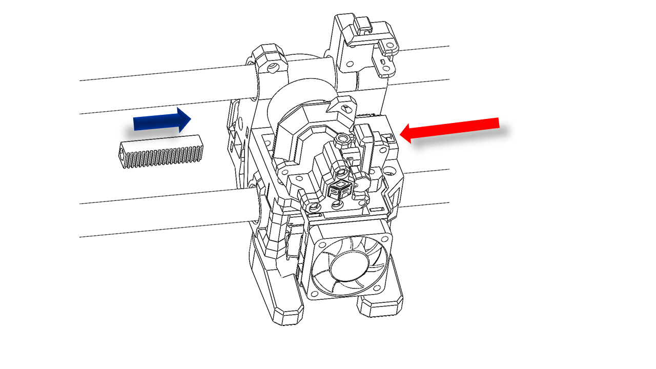
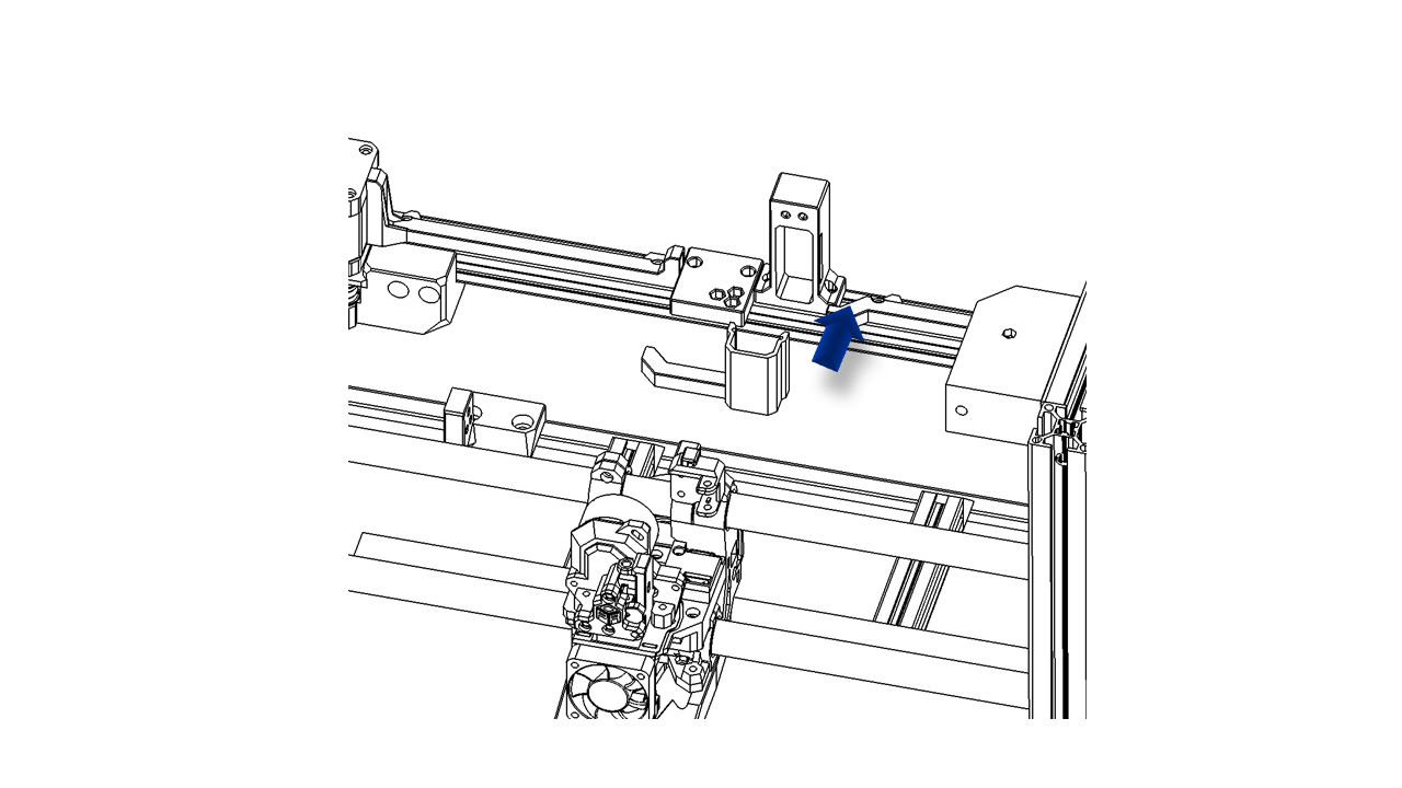
- The other belt requires an extra belt support. Insert the GT2 belt as shown. The belt comes out of the mount as the blue arrow.
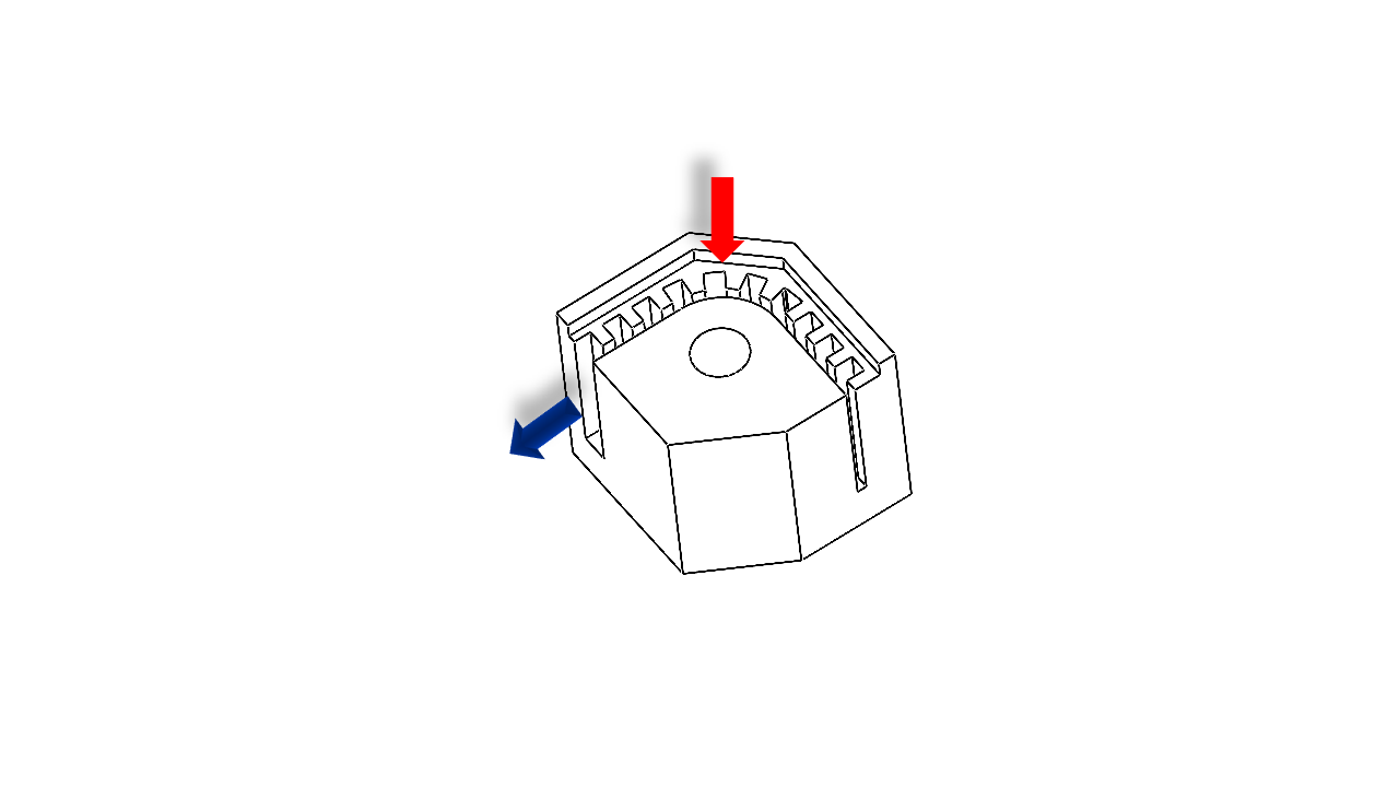 .
.
- The belt mount can be fitted in the slot of the tool head, as shown.
 .
.
- Then slide in the belt support to fix the belt.
 .
.
- Tighten the structure using M3 x 45.
 .
.
4.1.5 Fan install
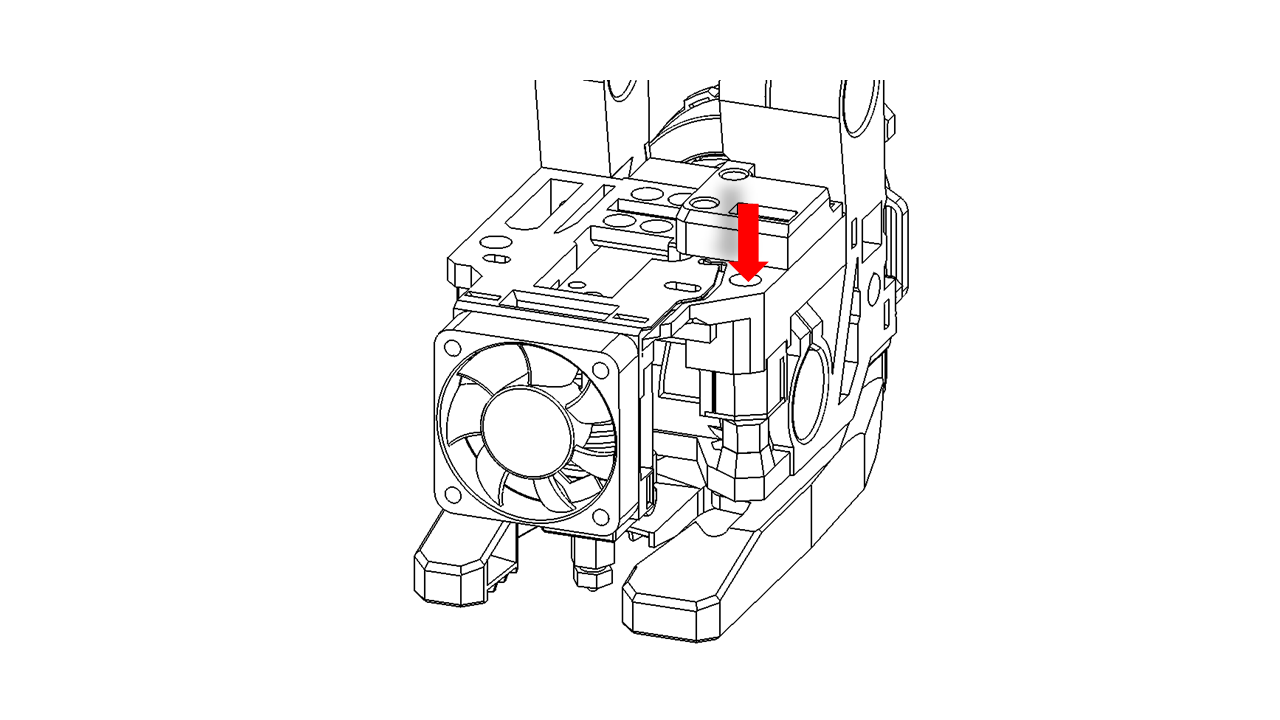
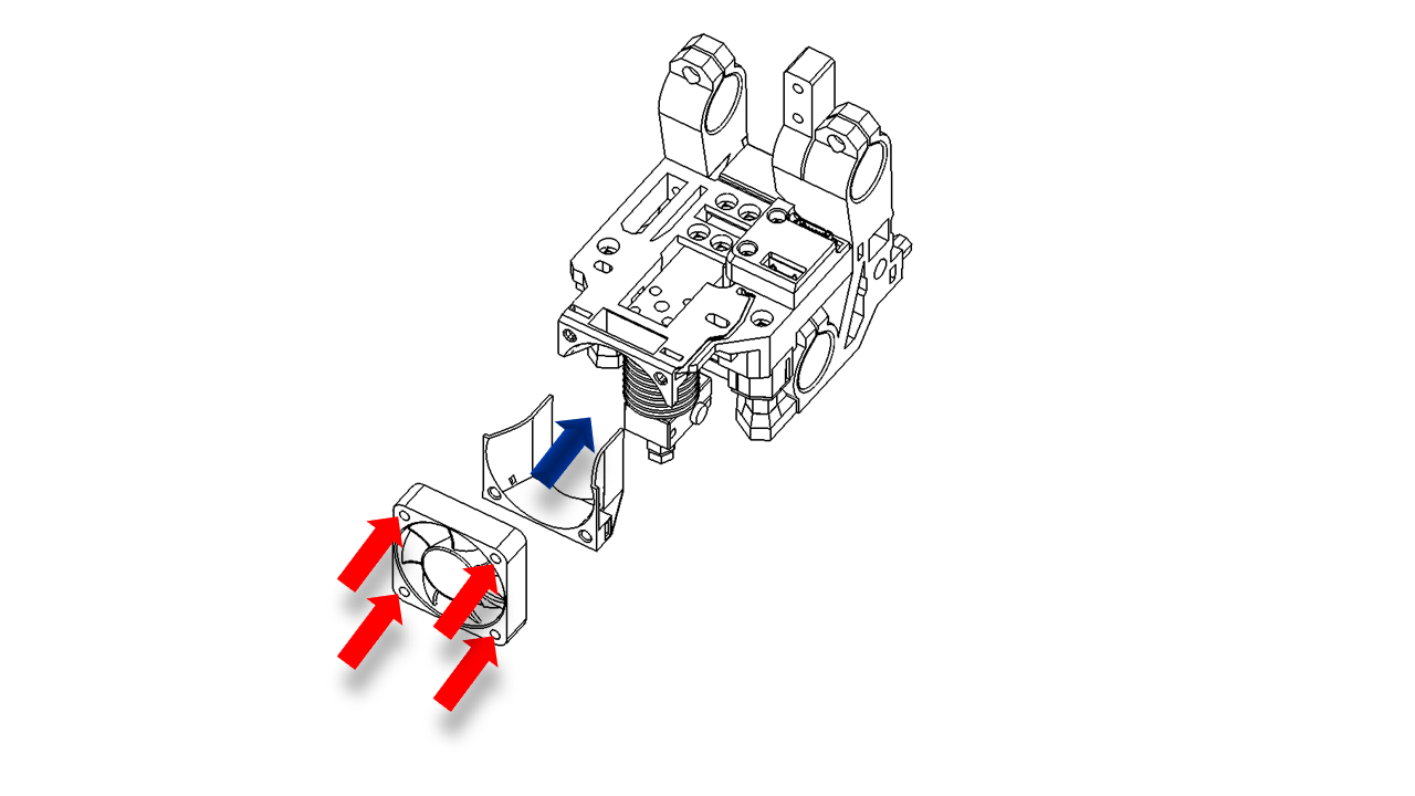
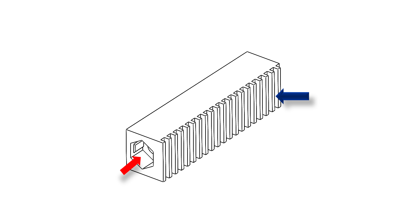
- Now it's time to install the heat sink fan. Place the part as shown and use M3 x 18 to tighten the fan. Note that the fan wires should come from the top of the fan.
 .
.
-
Take the blowing fan duct and mount it at the back. Attach them with M3 x 16 screws. Make sure the fan duct can slide up and down.
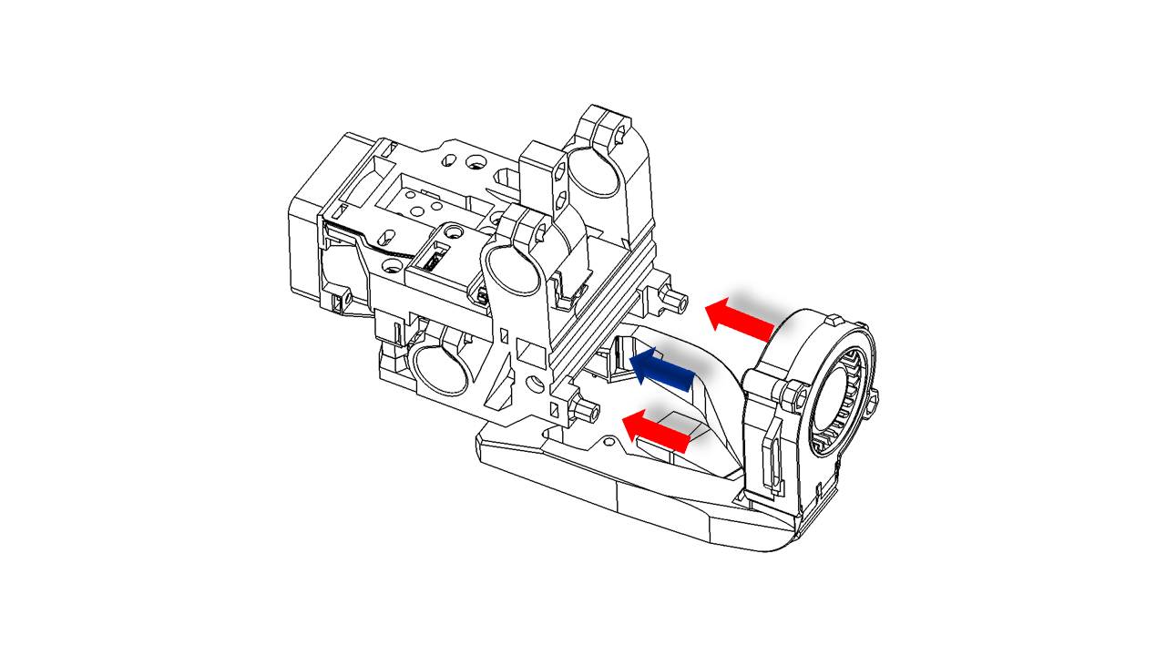 .
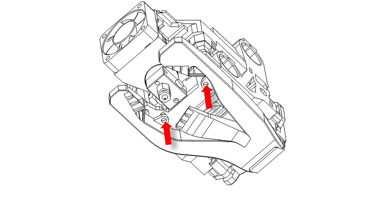
. -
There are two screws below; use M3 x 14 screws. Use a 5 mm washer if you use the default nozzle set (E3D V6), then tighten them to make sure the fan duct is at the correct location. Once you are done, tighten the screws at the back to fully fix the fan duct.
 .
.
4.1.6 Final assembly
- Install the drag chain mount using M3 x14 screws.
 .
.
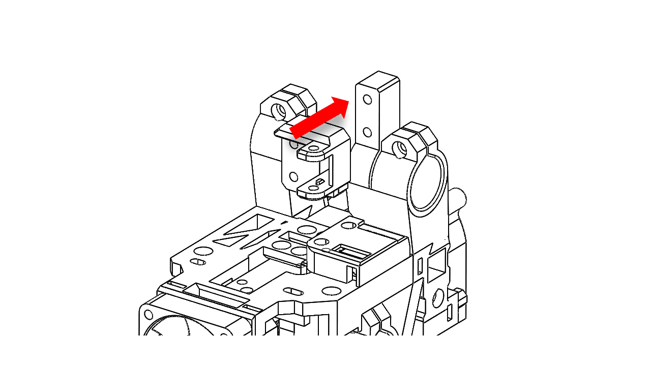
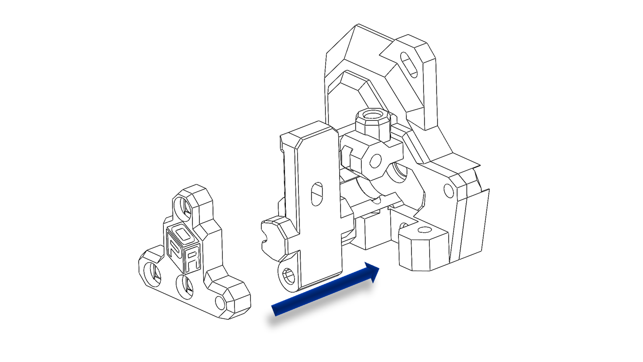
4.1.7 Extruder
-
For P350, you can use some out-of-the-shelf extruders, such as Sherpa Mini.
-
Before we assemble the extruder, we need to prepare the printed parts and gears first.
-
First, we need to put the extruder gear with set screws on the shaft. Tighten the set screw.
-
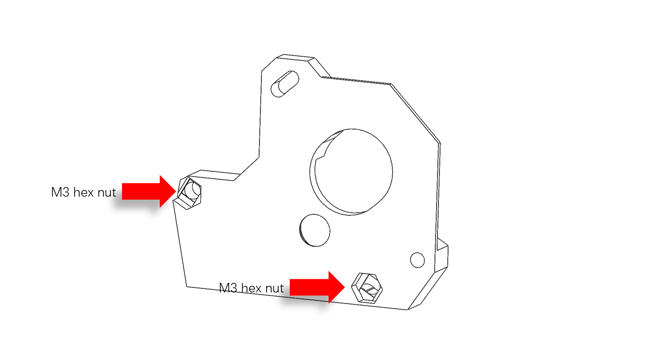
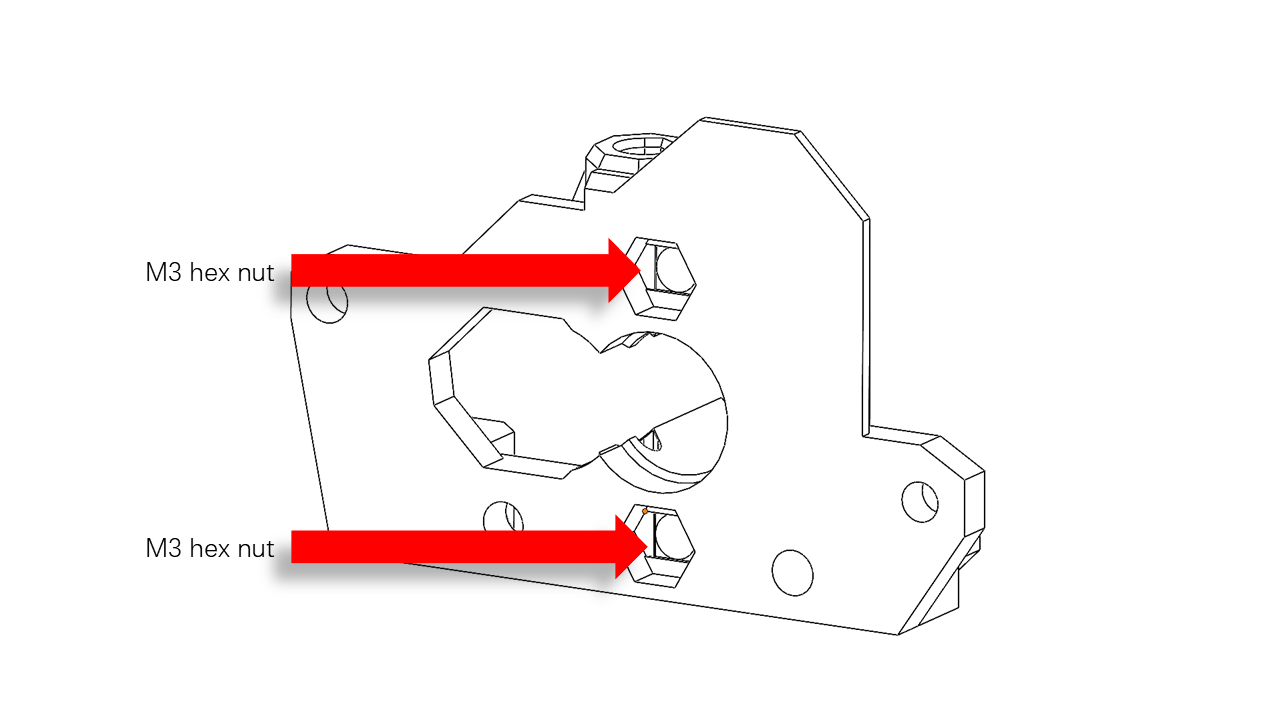
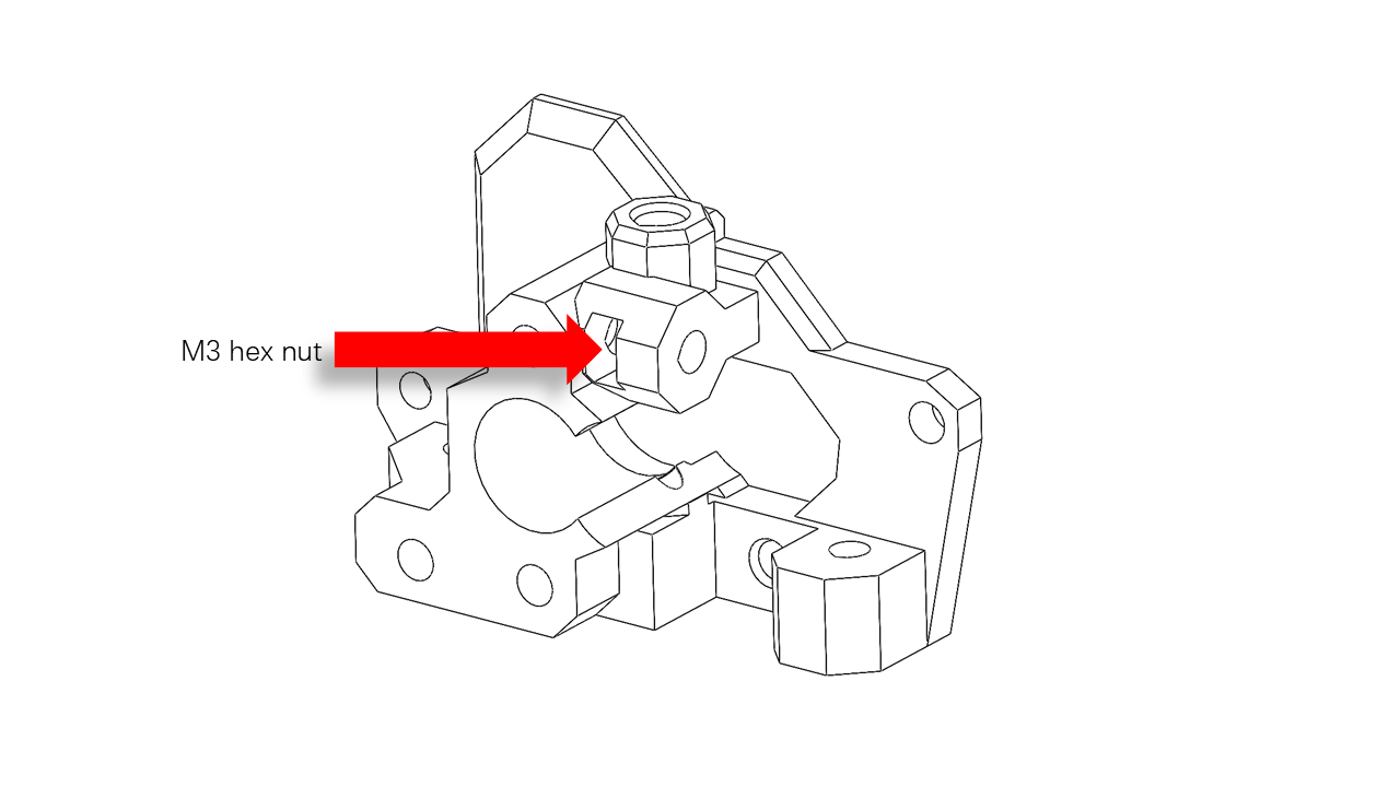
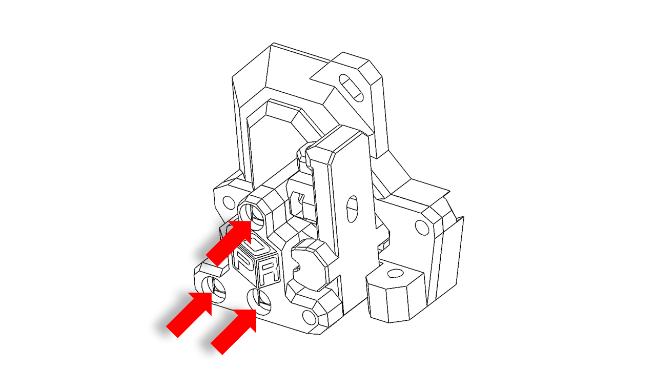
Pre-insert M3 hex nut on printed parts at these locations.
 .
.
 .
.
 .
.
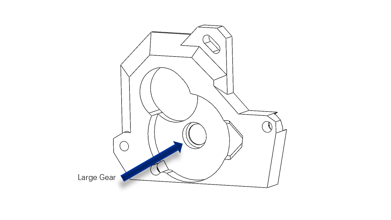
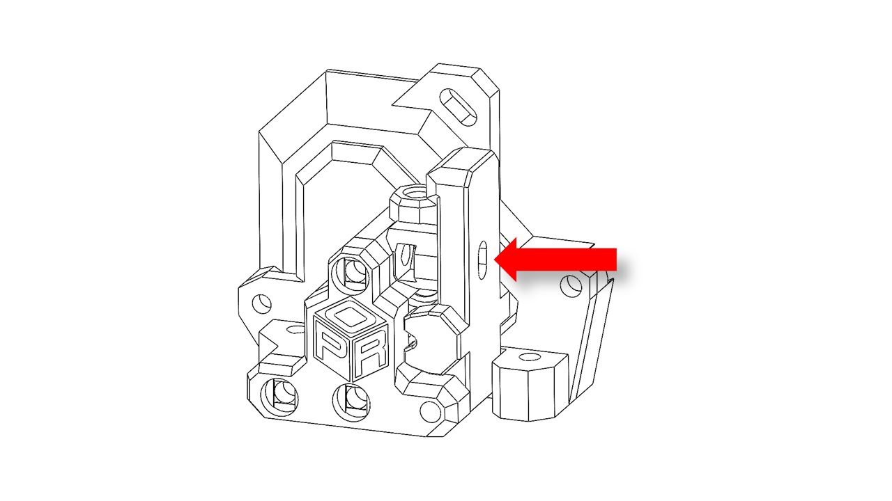
- Put the ball bearing on the end with the large gears, and put the gear set into the slots as shown.
 .
.
- Assemble the printed parts as shown.
 .
.
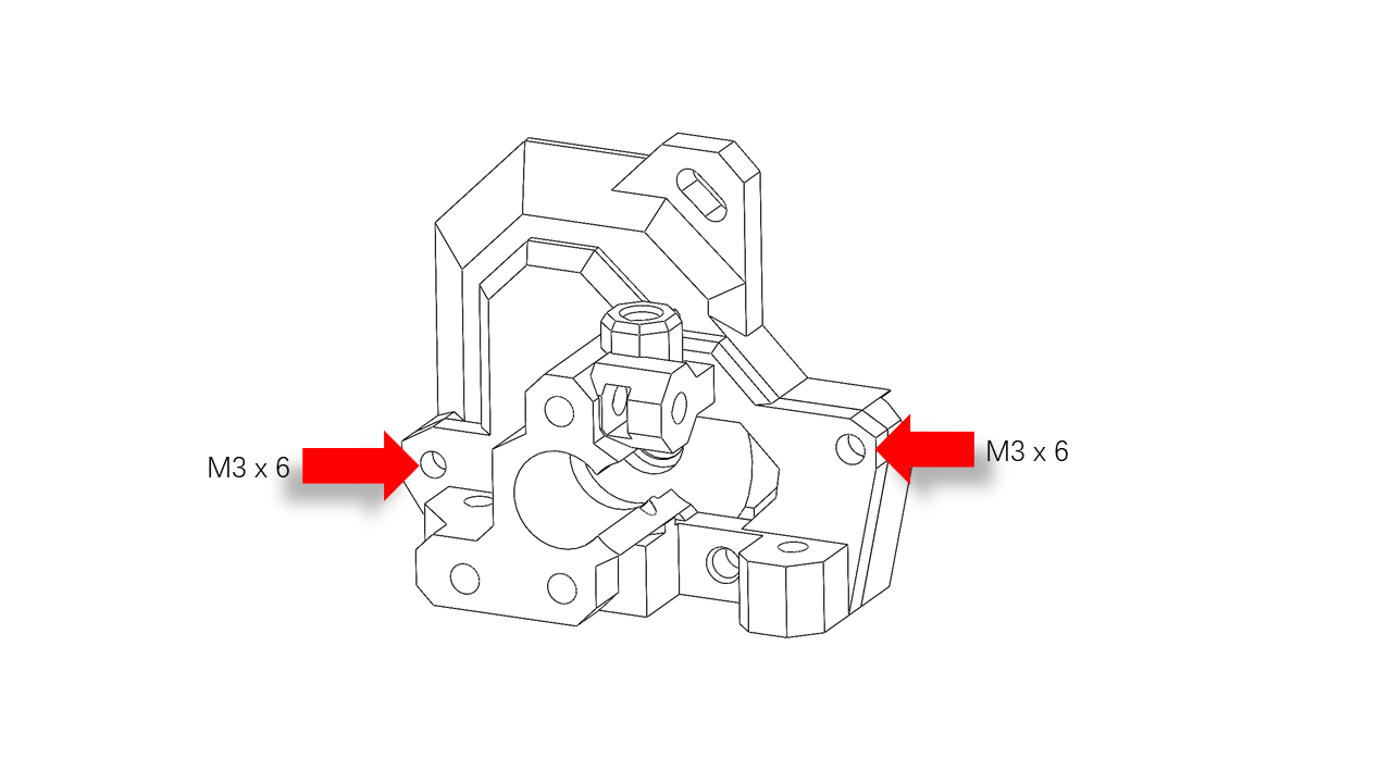
- Use M3 x 6 screws to fix the printed parts as shown.
 .
.
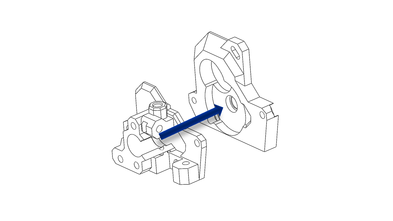
- Press Insert the other gear with the shaft here.
 .
.
- Insert the shaft and assemble the rest of the extruder as shown.
 .
.
- Use the long M3 screws to fix the printed part.
 .
.
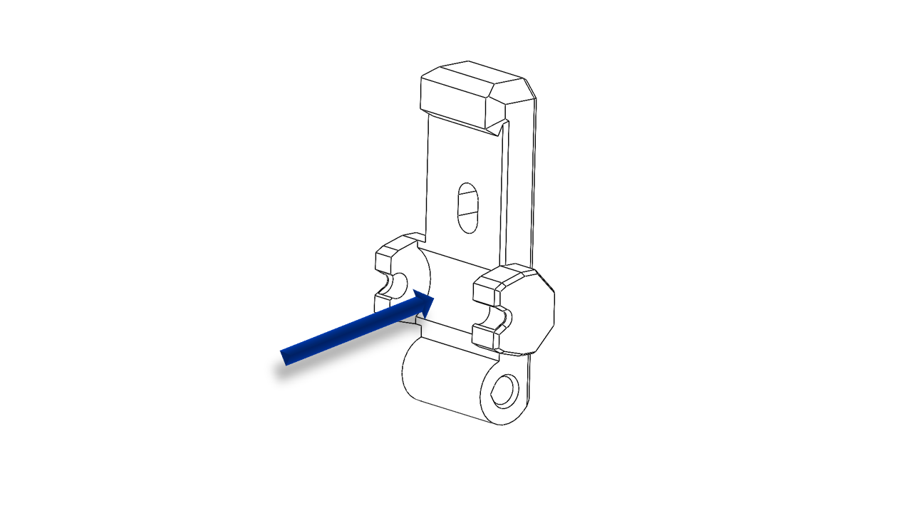
- Put the spring on the nob and insert the nob as shown.
 .
.
- Install the extruder motor as shown.
 .
.
- Adjust the extruder motor to make sure the gears are meshed properly.
 .
.
- Insert PTFE tube here, note the tube have chamfered. The chamfer should point upwards.
- Install the extruder with an M3 x 15 screw as shown. Adjust the slider block to make sure the screws are aligned.
 .
.
4.2 Attach the tool head
4.2.0 Assemble
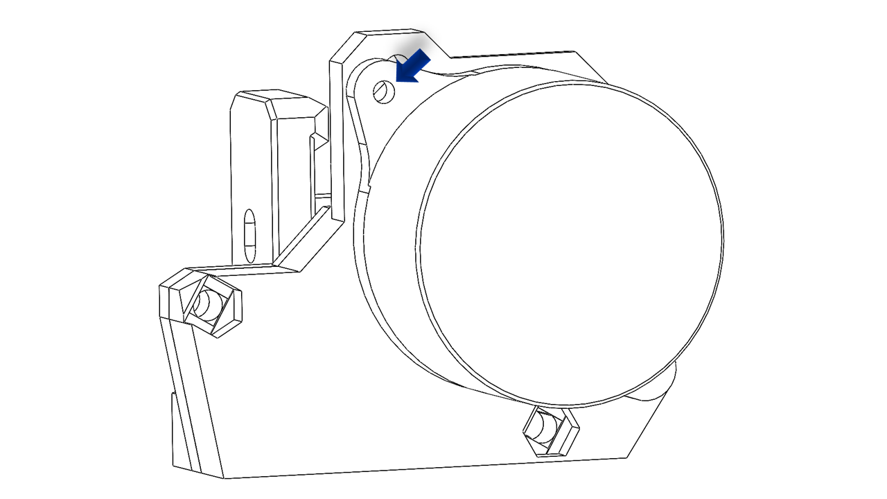
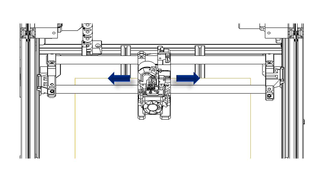
- Now, release the screws on the X axis as shown and slide the carbon tube to the right.
 .
.
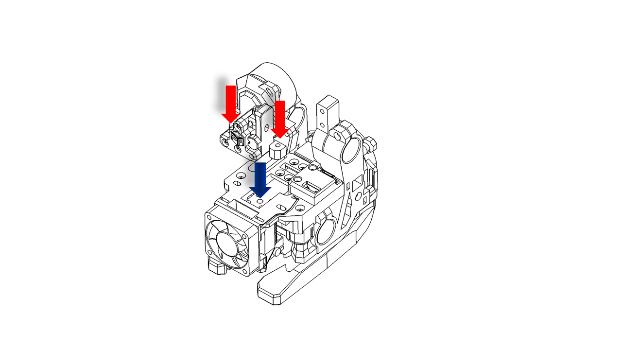
4.2.1 Attach the Tool head
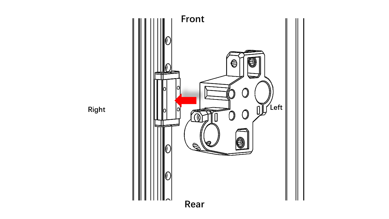
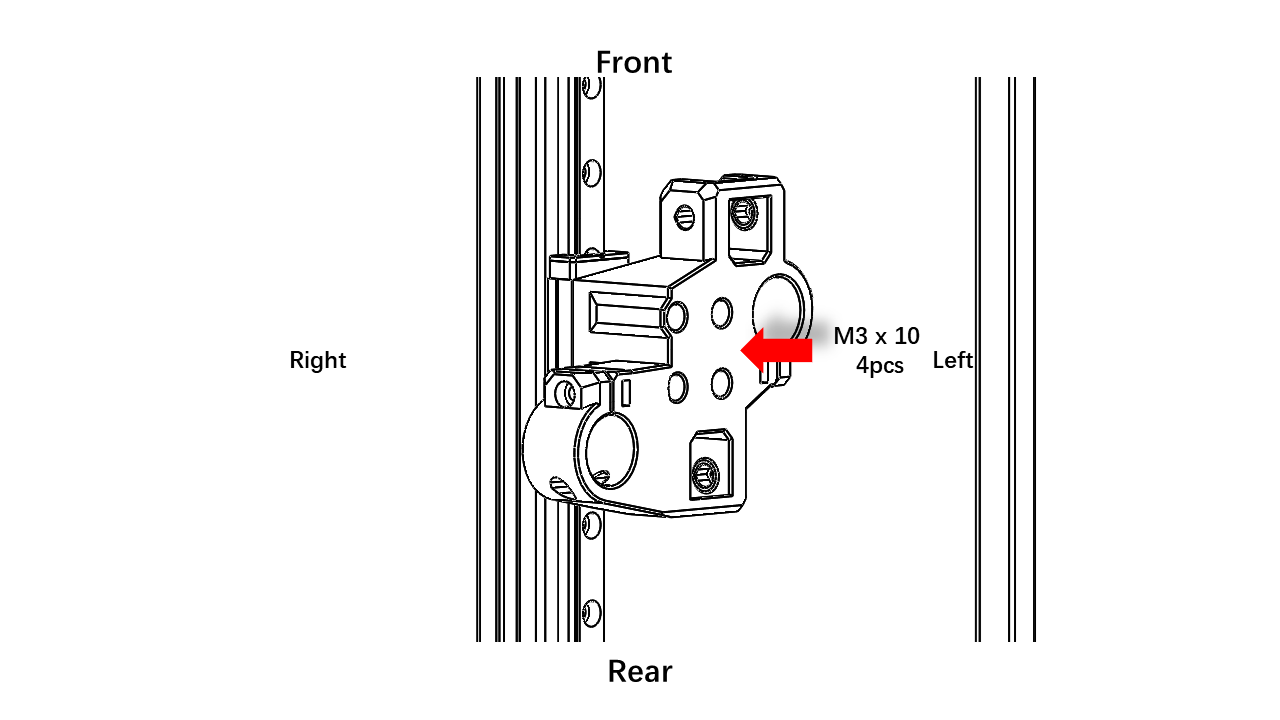
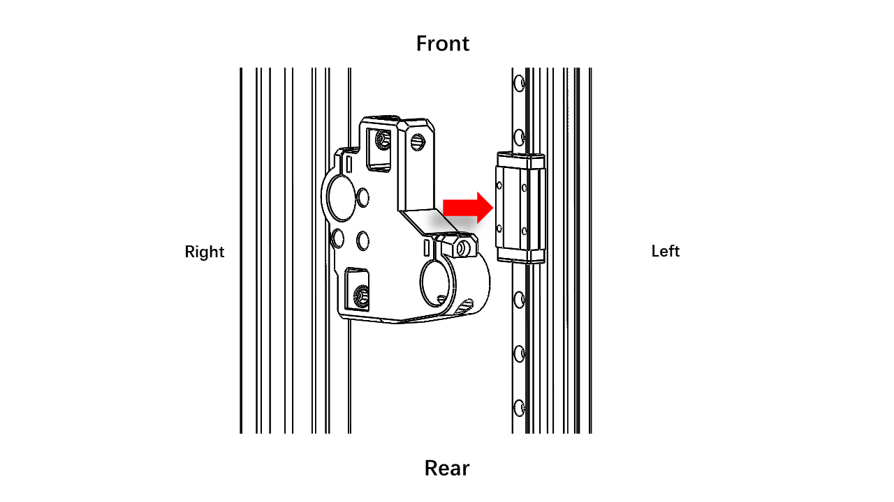
- Slide the tool head on the carbon tube onthe X axis. Tighten the screws.
 .
.
- Slide the tool head left and right, making sure it moves smoothly.
 .
.
4.3 XY Belts
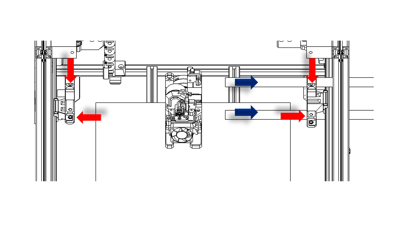
4.3.0 Assemble
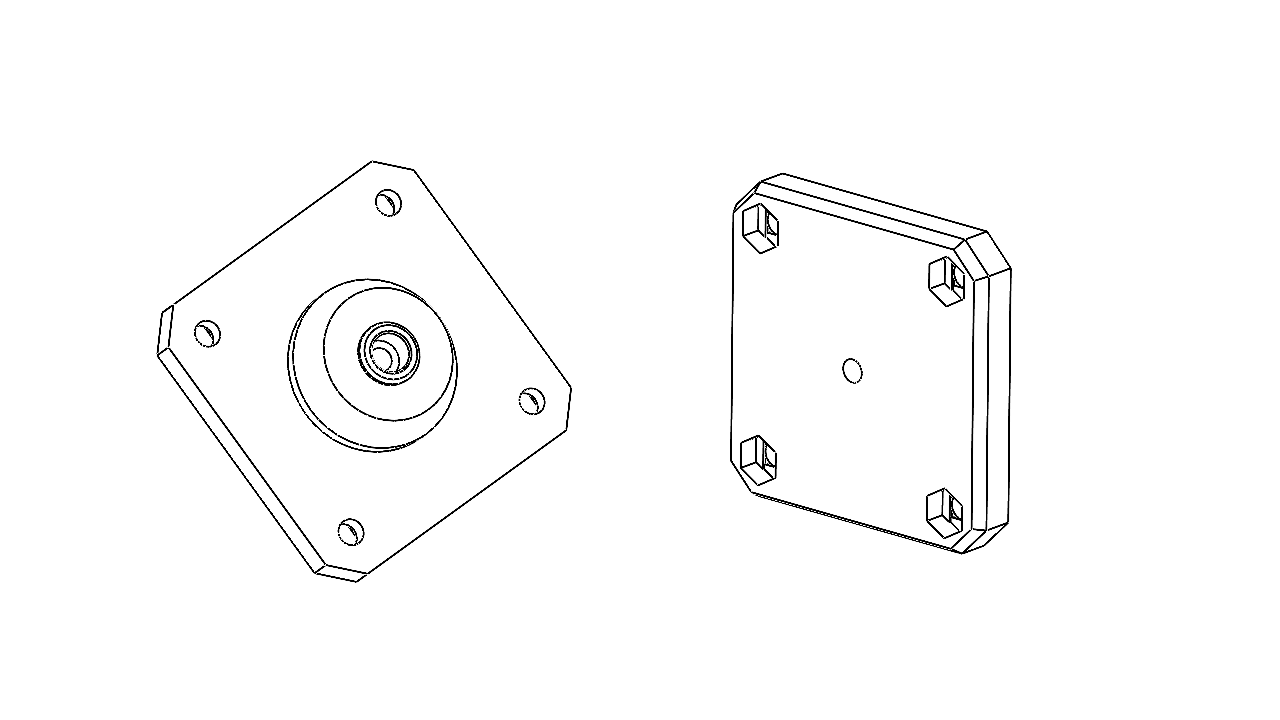
- Pre-insert the bearings with the pin(4.95 x 20) at the following positions. You can use a hex key as a pin guide to help you align the bearings.
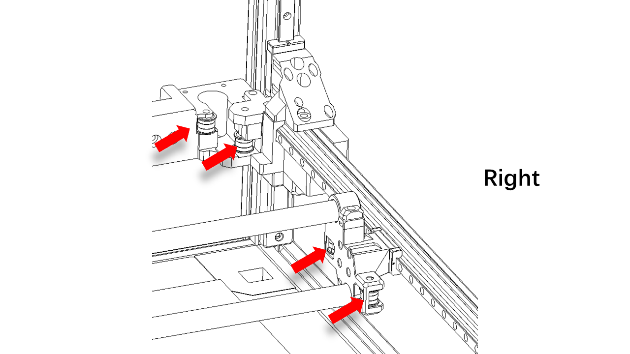 .
.
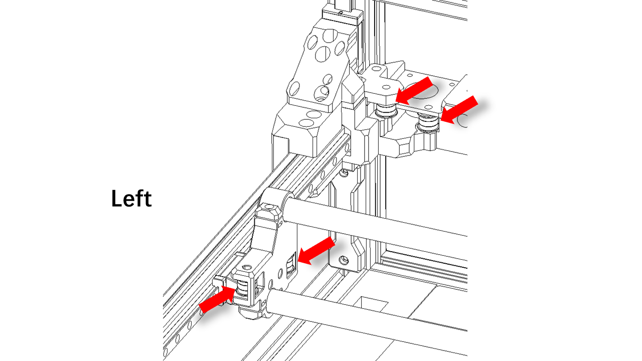 .
.
- For the front bearings the things will be a little different. Find these printed parts and pre-insert the M3 nylon nut.
 .
.
 .
.
- Then use M3 x 50 screws to fix the bearings as shown. Note the orientation.
 .
.
 .
.
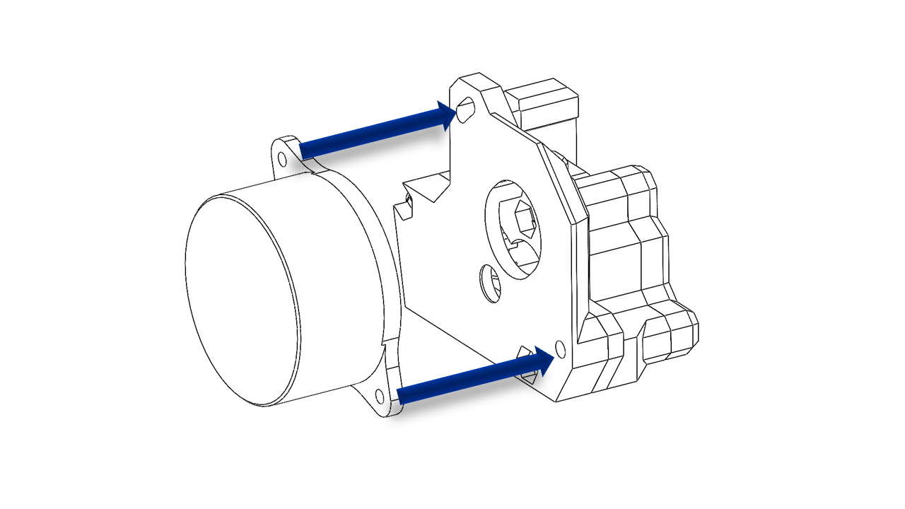
4.3.1 Mount the motors
-
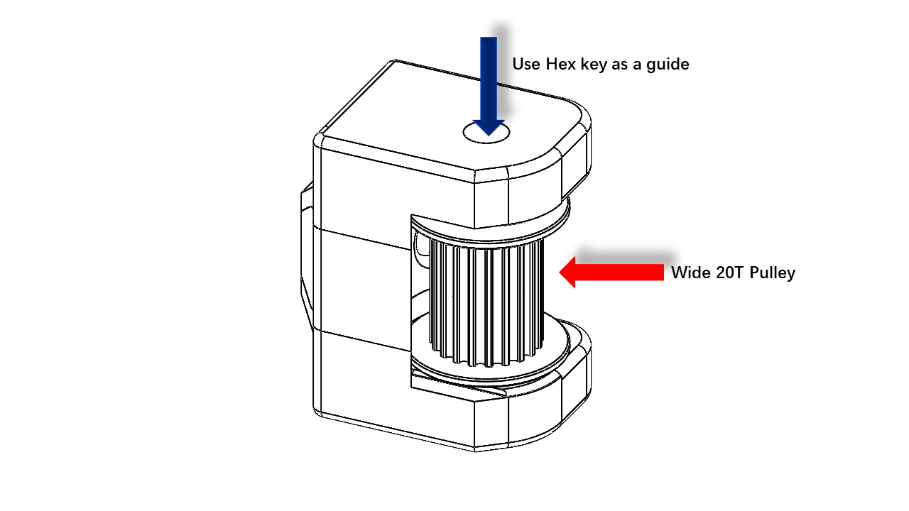
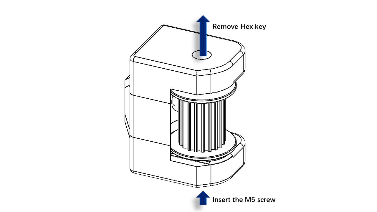
First, take the AB motor and use a jig to mount the pulley in the correct place. Tighten the screw. Make sure you tighten all set screws.
 .
. -
Assemble the motors use M3 x 8 screw as shown. Note the orientation, the wires should come towards the inside. (shown by the blue arrow)
 .
.
 .
.
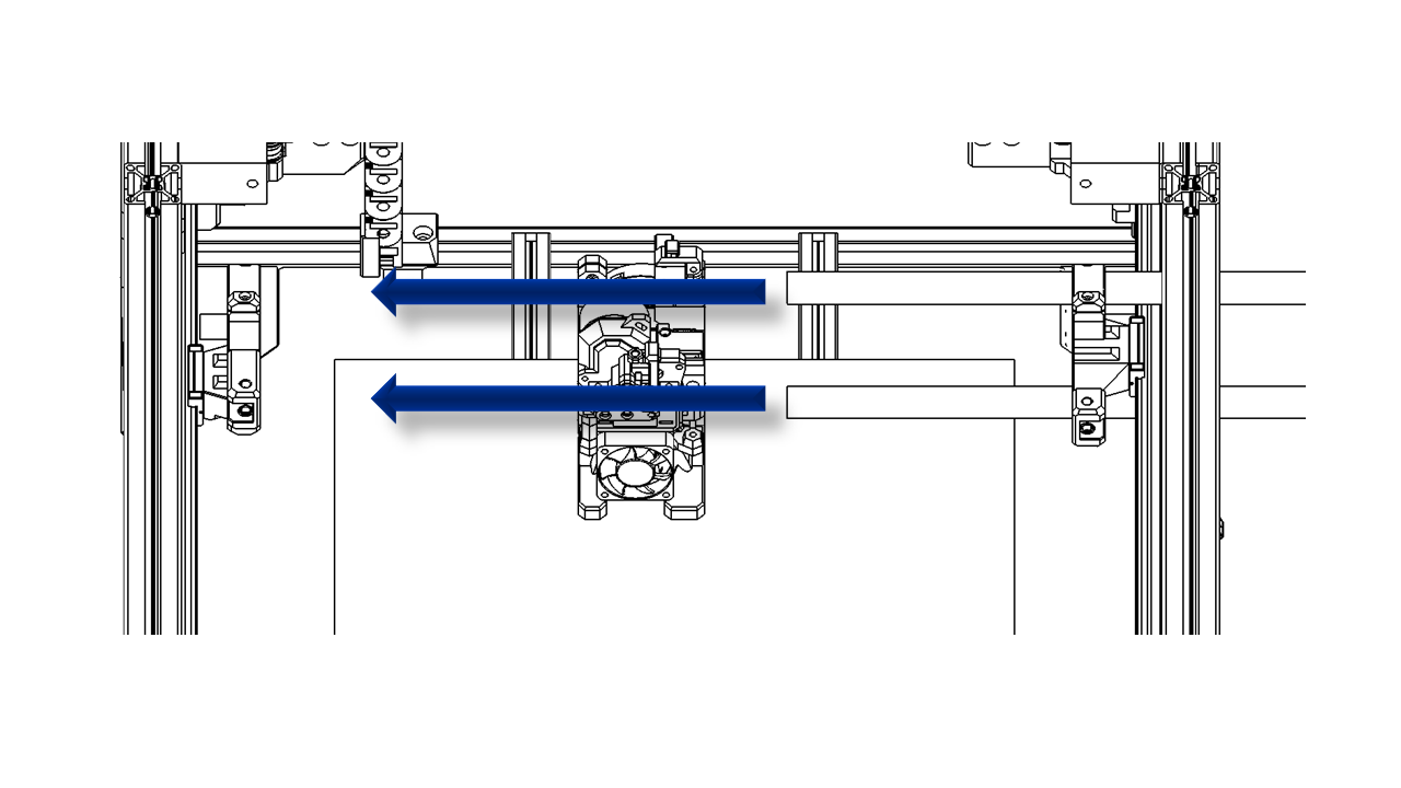
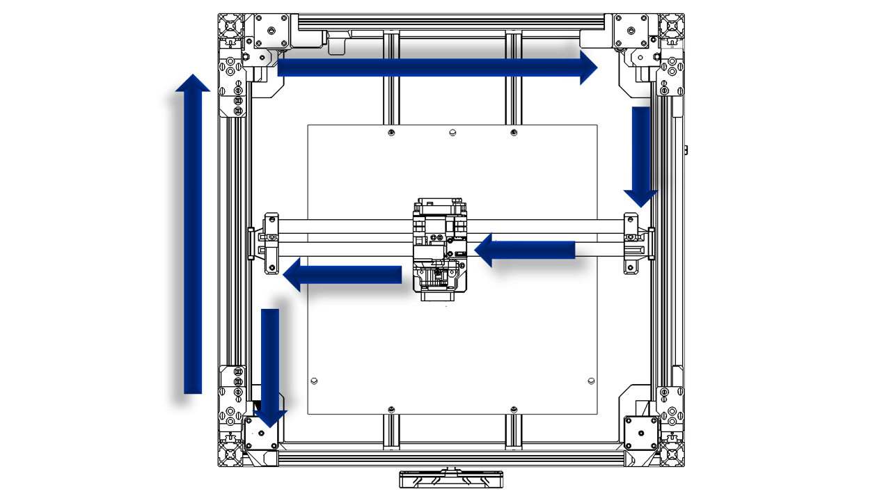
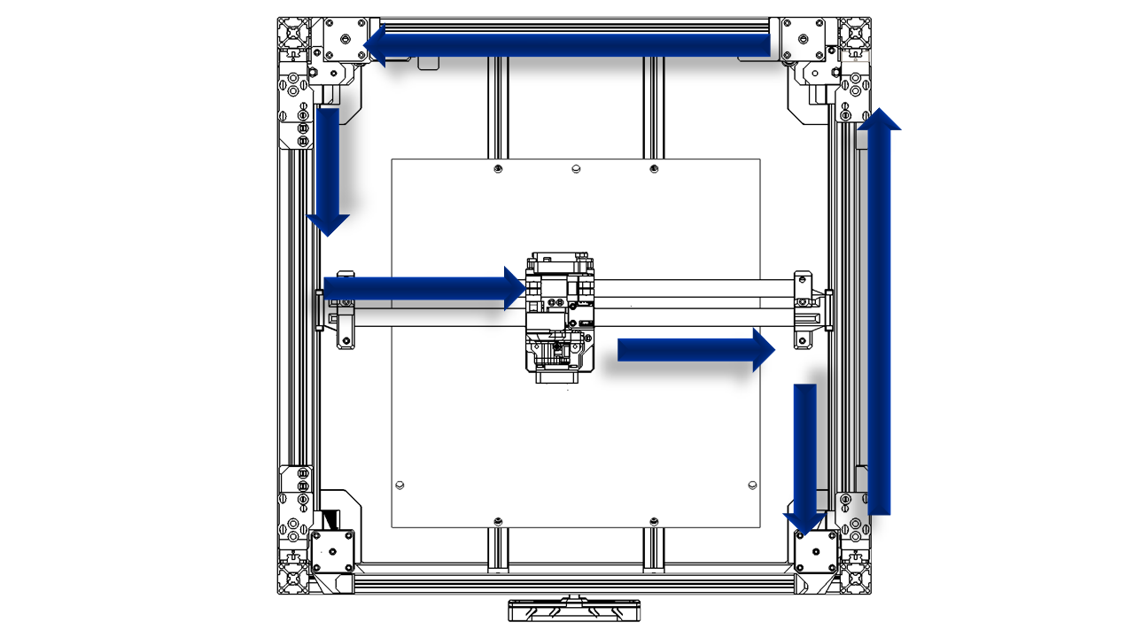
4.3.2 XY belt
-
Now, let us do the belts. Since we pre-insert the belts on the tool head, the rest will be pretty easy.
-
Warp the belts as shown.
 .
.
 .
.
-
Take the belt clip, insert the M3 nylon nut as shown. The belt should fully match the teeth on the clip.
 .
. -
Insert the Belt clip as shown. Note the direction.
- Use an M3 x 60 screw to apply tension on the belt as shown. Do not over-tighten the belts.
 .
.
 .
.
4.3.3 Wire guide assembly
- Pre insert Nylon nut on the hex slots and hang the T-nut (3030 M5) with M5 x 10 screws.
 .
.
- Pre insert Nylon nut on the hex slots and hang the T-nut (2020 M3) with an M3 x 10 screw.
 .
.
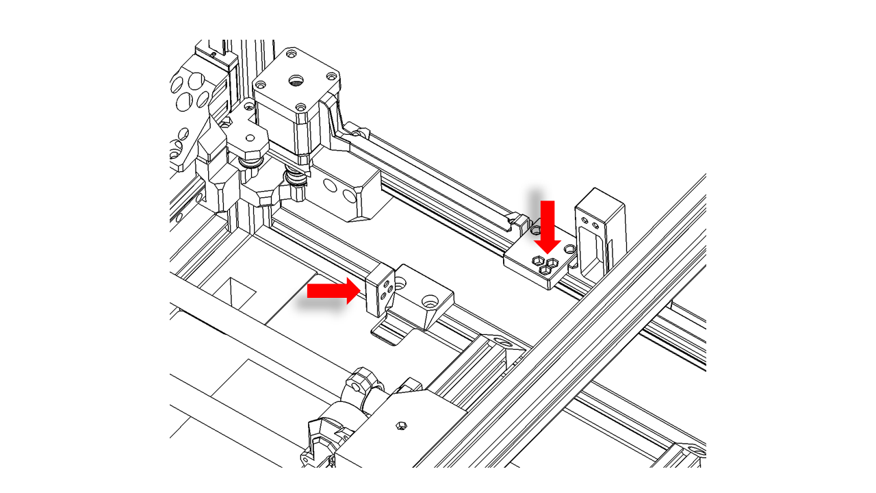
- Install the mount as shown, do not fully tighten them yet. We will adjust the position later.
 .
.
- Install the chain mount as shown, do not fully tighten it yet. We will adjust the position later.
 .
.
- Use M3 x 10 screws to fix the truck chain. The tool head has a place for the chain. Clip the chain on the tool head. The wire slot should be facing outwards.
 .
.
 .
.
- Insert M3 x 10 screws and hang the T-nut (2020 M3) on the motor wire covers.
 .
.
- Install the motor wire cover, making sure the motor wires are fully hidden inside.
 .
.
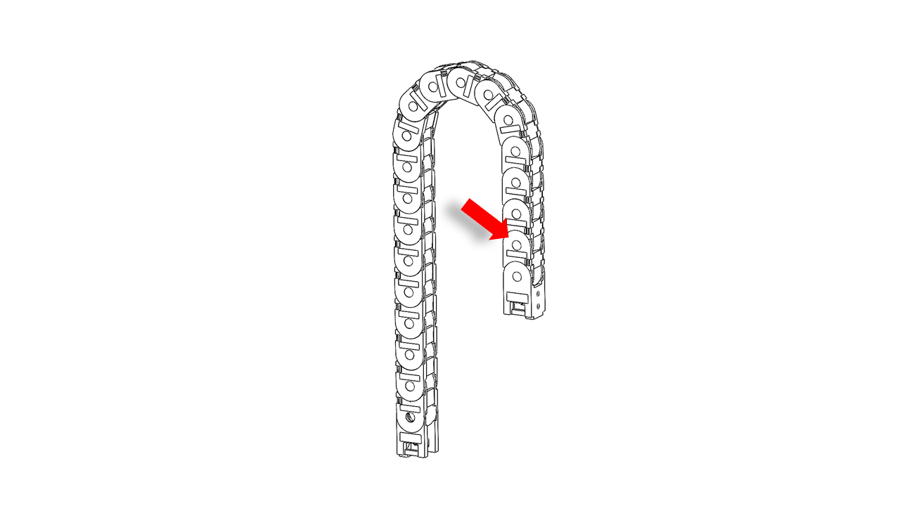
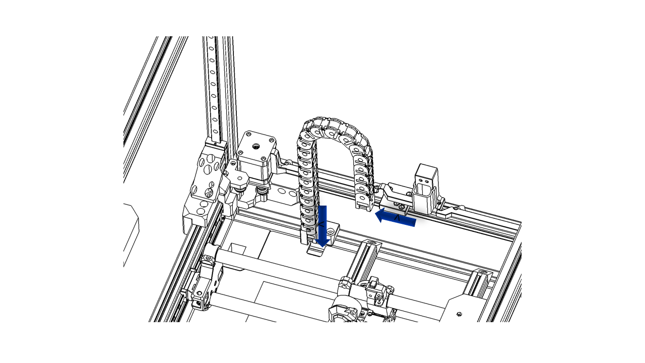
- Take the large chain, take off the last two sections, and install them in reverse.
 .
.
- Install the large chain as shown. Note that the reversely installed part should be mounted on the gantry.
 .
.
4.3.3 Wires
- The front fan wires should be pressed into the slot on the tool head, as shown.
 .
.
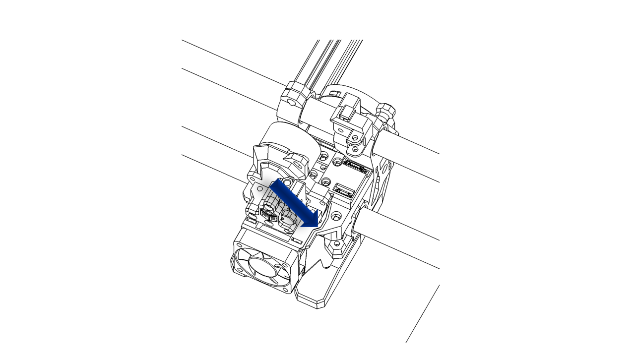
- The turbo fan wire should go through the wire guide as shown.
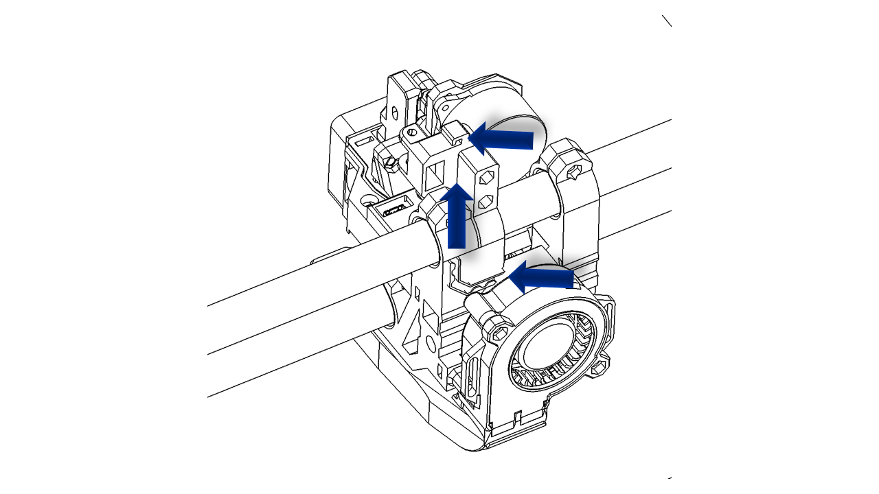 .
.
-
All wires on the tool head should fit in the chain. Use a zip tie to make sure the wires do not fall out during movements.
-
Sort the wires and pass them through the large chain. These wires should pass through the square hole on the bottom plate.
 .
.
- Sort all the wires and cover them as shown. This wire cover can be clip on the wire guide mount directly.
 .
.
4.3.4 Check
Move the tool head in X and Y full range to make sure the wire guide is ok. Move the Z axis up and down to make sure the wire guide does not jam or having sudden move.
5. Heated Bed
5.1 Assemble the structural support
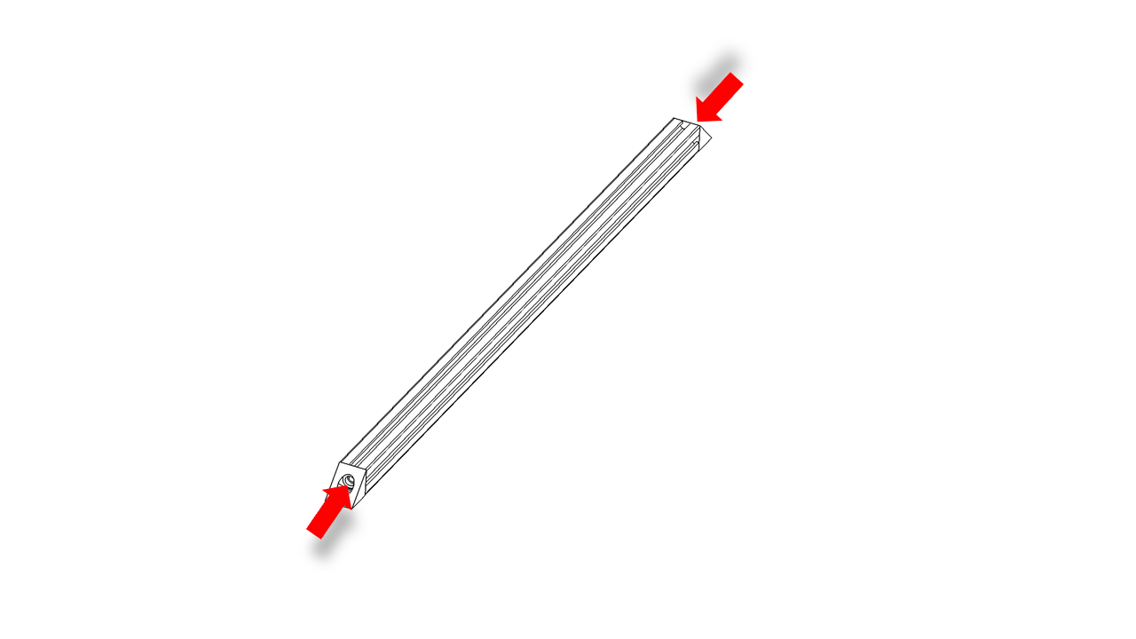
- Prepare the profiles. Use M5 x 16 screws to fix the corner fix on the profiles as shown. Do this for both 506mm 2020 profiles.
- Then insert the M5 x 10 screw and hang the T-nut (3030 M5) for later use.
 .
.
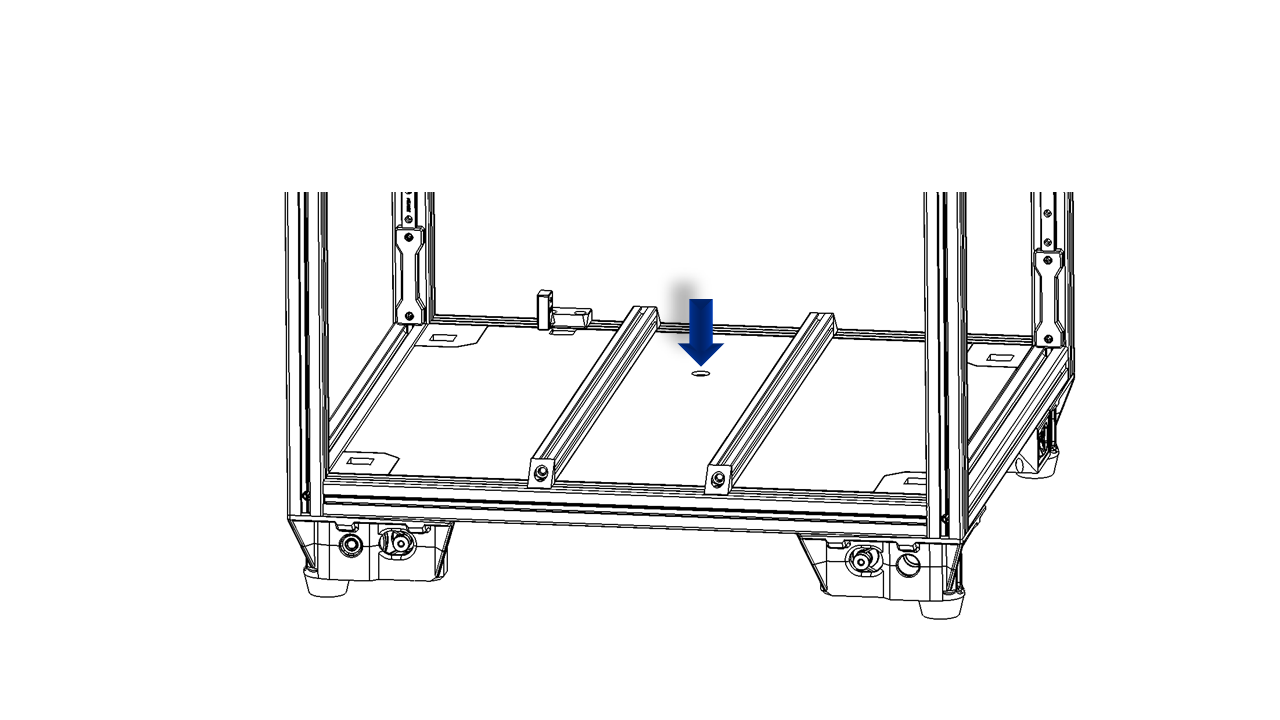
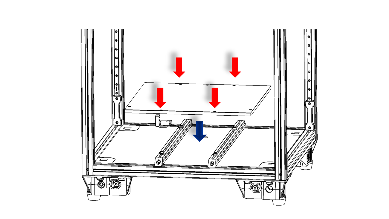
- Put the bottom plate on the frame. It should fit nicely.
 .
.
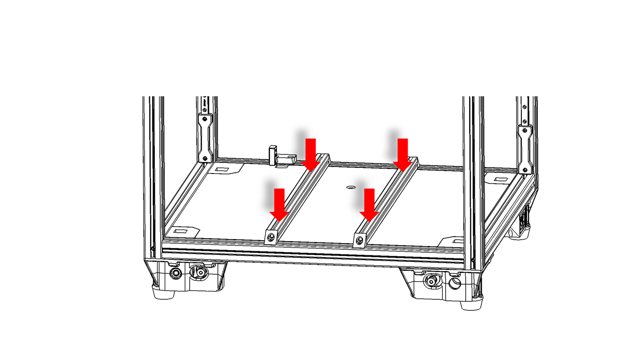
- Fix the 2020 profiles on the bottom frame. You should use jigs to help you find the correct locations. Do not fully tighten the screws yet, as we may do some adjustments later.
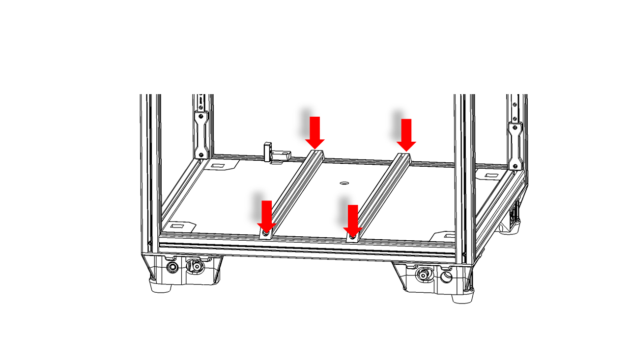 .
.
- Pre-insert the 2020 M3 spring nut into the 2020 frame for later use.
 .
.
5.2 Prepare the heated bed
-
Now it is time to prepare the heated bed.
-
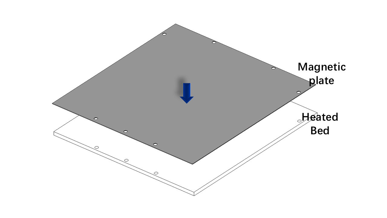
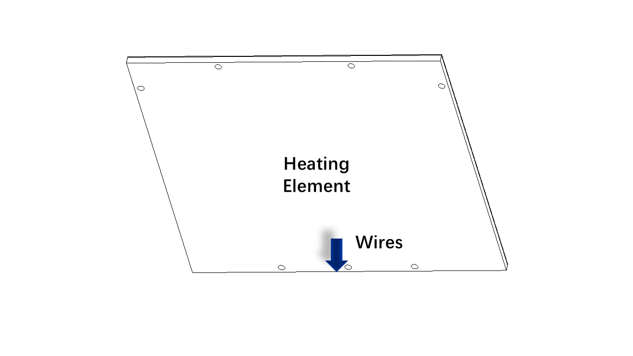
Stick the heating element on the aluminium heated bed. Note the orientation. Make sure it is in the center of the heated bed.
-
Stick the magnetic plate on the heated bed as shown. Note the orientation. The holes should match the ones on the aluminium plate.
 .
.
 .
.
- Put all wires of the heated bed through the round hole on the bottom plate as shown.
 .
.
- Use M3 screws to fix the heated bed. Note that the heated bed is supported by these M4 nuts. Slightly tighten the screws.
 .
.
-
Adjust the position of the heated bed with jigs. Tighten all the screws.
-
Put the spring steel sheet on the heated bed.
5.3 Check
- Use the jig to check if the bed is in position. Once you are done, make sure the heated bed is fixed and can not move.
6. Electronics
6.1 Prepare the wires
-
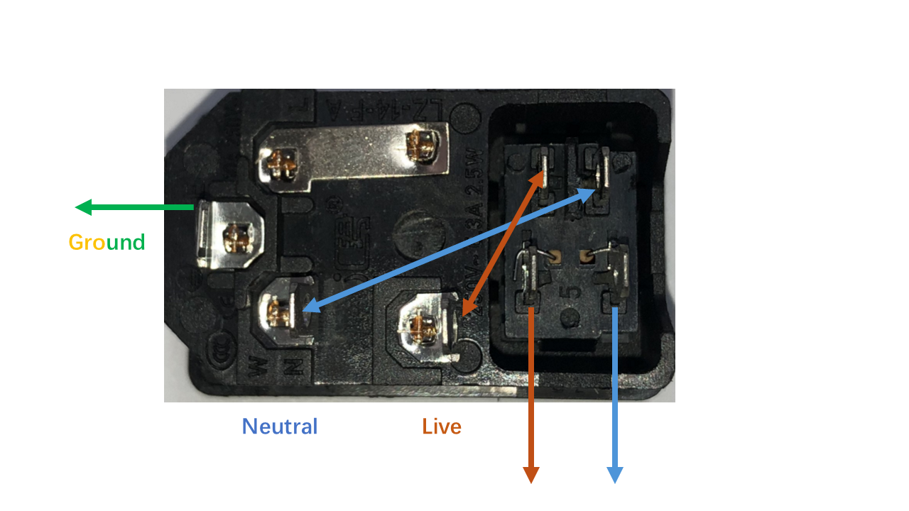
Note that wires are color-coded with the IEC 60446 standard.
-
For high-voltage wires:
- The Brown wires are Live wires
- The Blue wires are Neutral wires
-
The Yellow-Green wires are Ground wires.
-
For low voltage part:
- Red wires are positive.
-
Black wires are negative.
-
For signal wires:
- Note these wires are fragile; operate with caution.
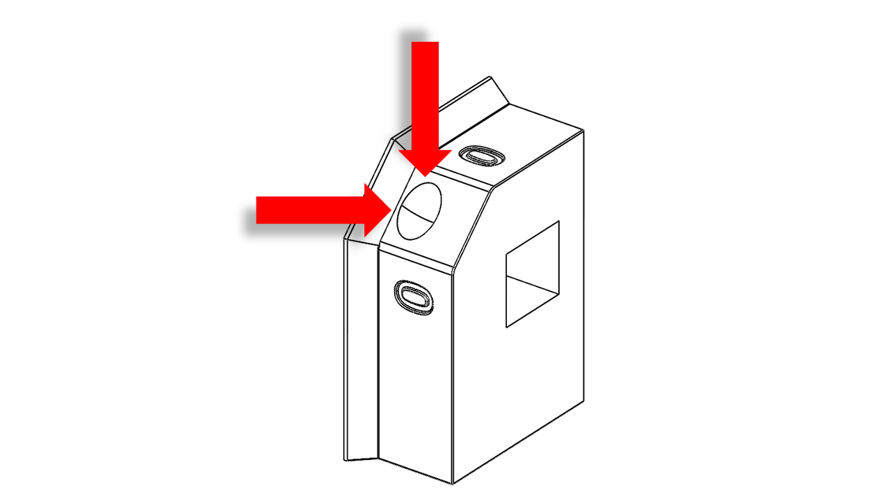
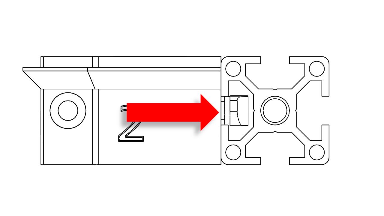
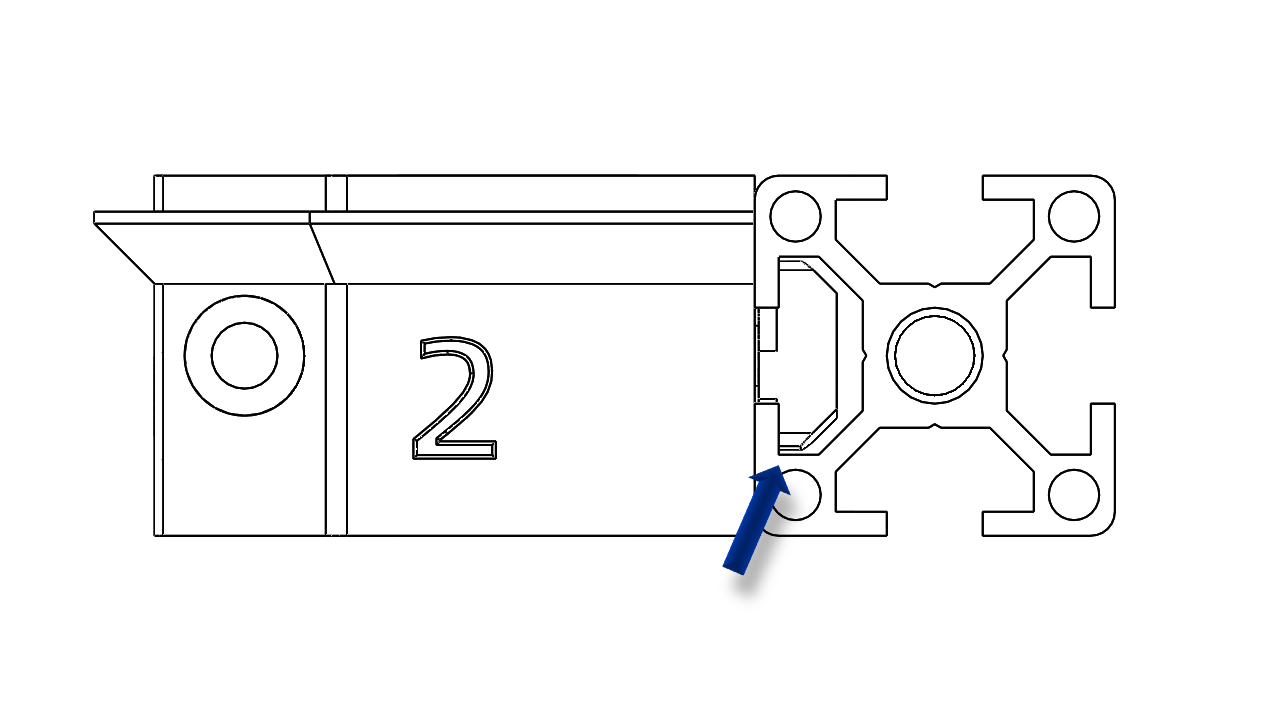
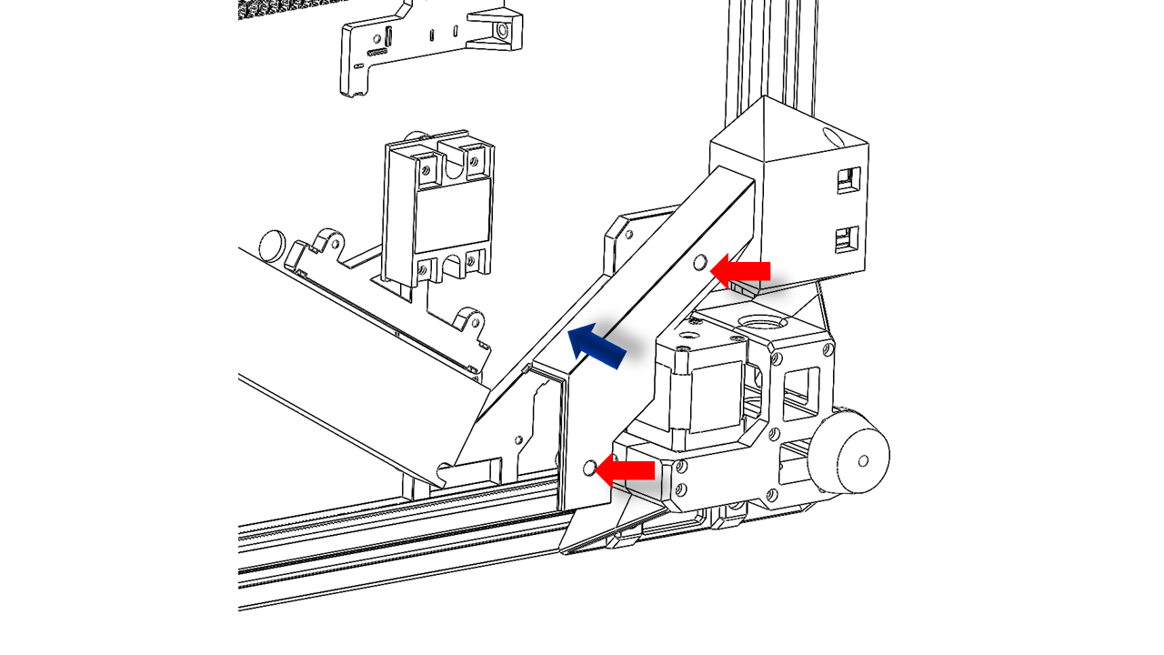
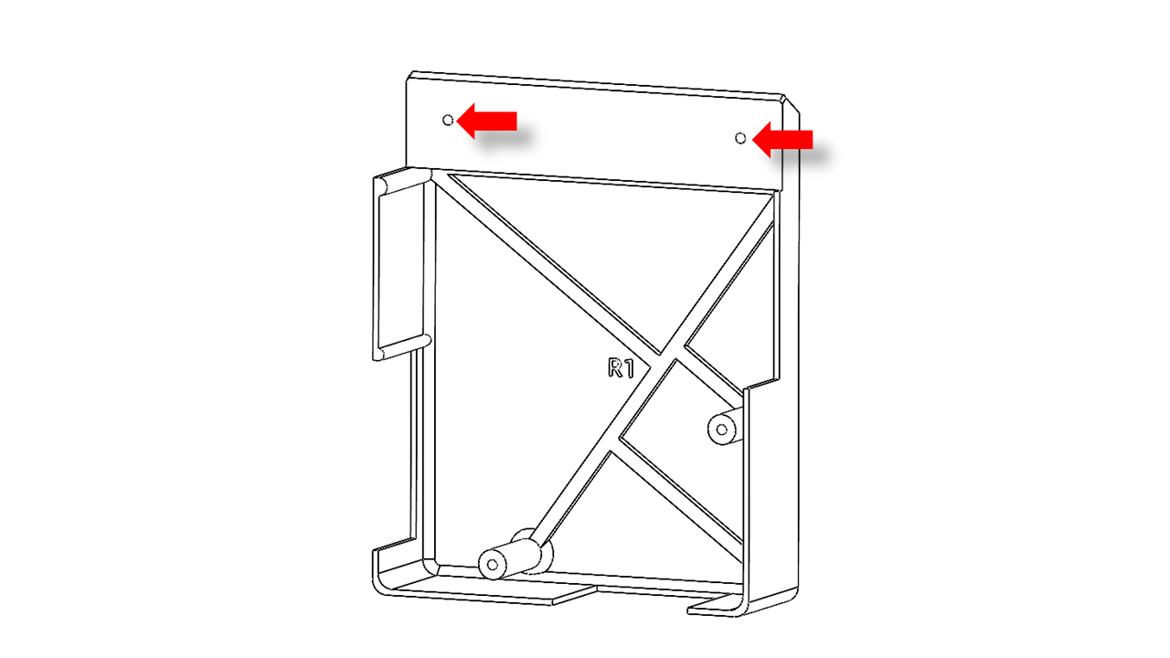
6.2 Assemble the power socket
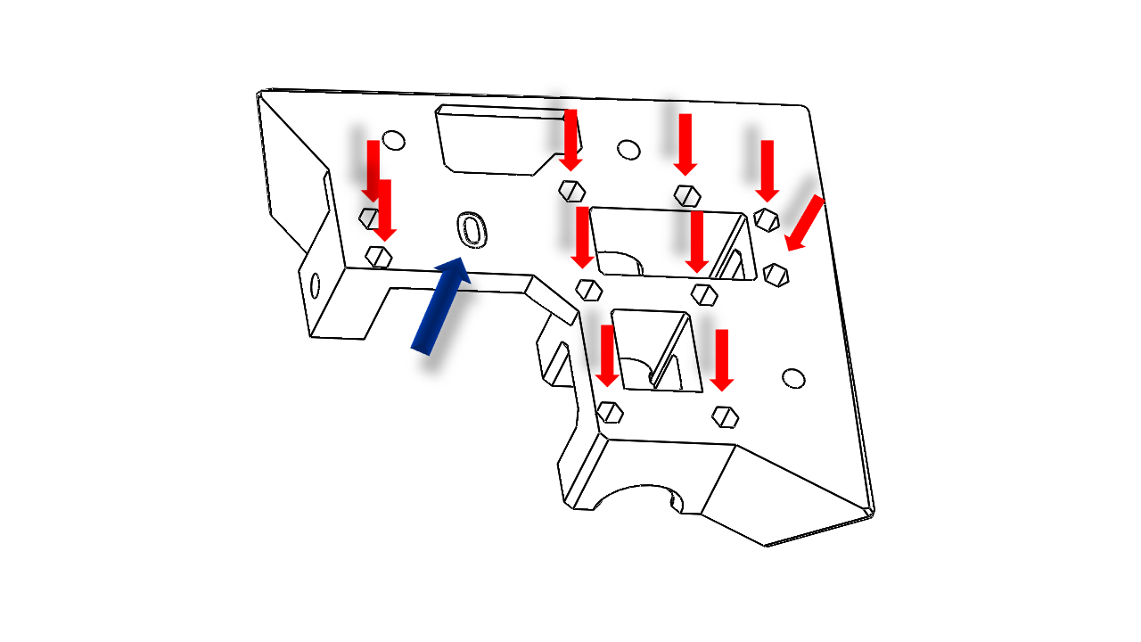
- Pre-insert the short wires in the power socket as shown(Double arrow). Note the color coding. Then install the long wires (Single arrow pointing outwards).
 .
.
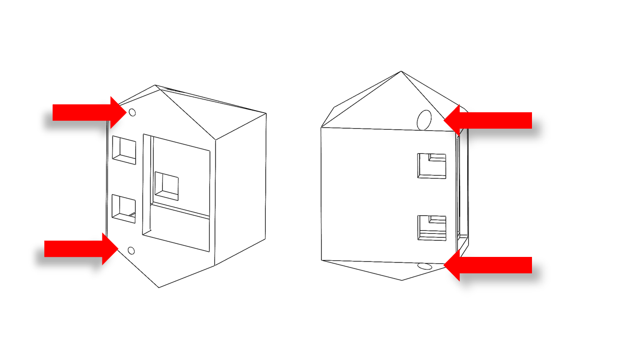
- Insert the M3x12 screws and then hang the T-nut (3030 M3) on the printed parts.
 .
.
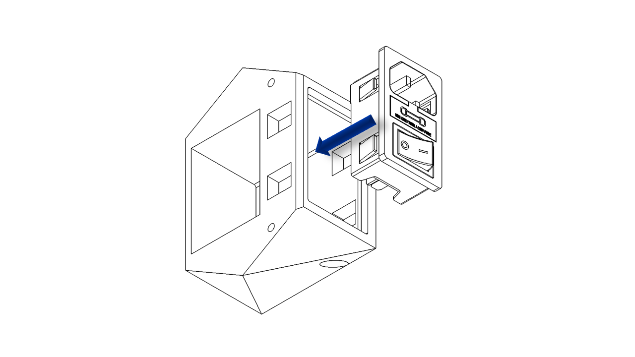
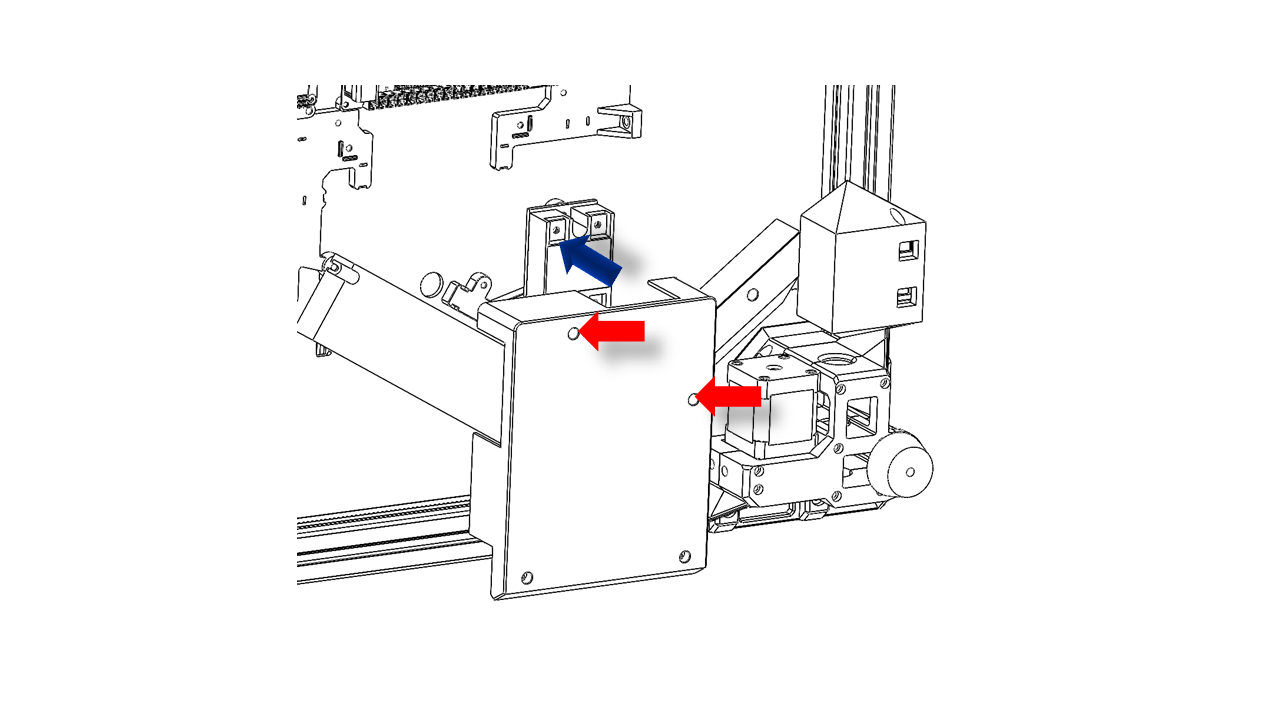
- Insert the power socket into the printed parts as shown. Pass the wires through the printed part for later use.
 .
.
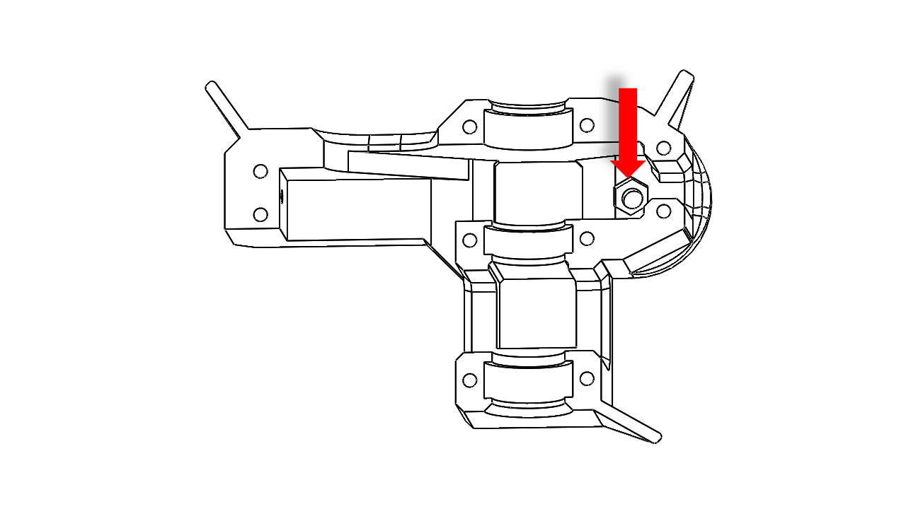
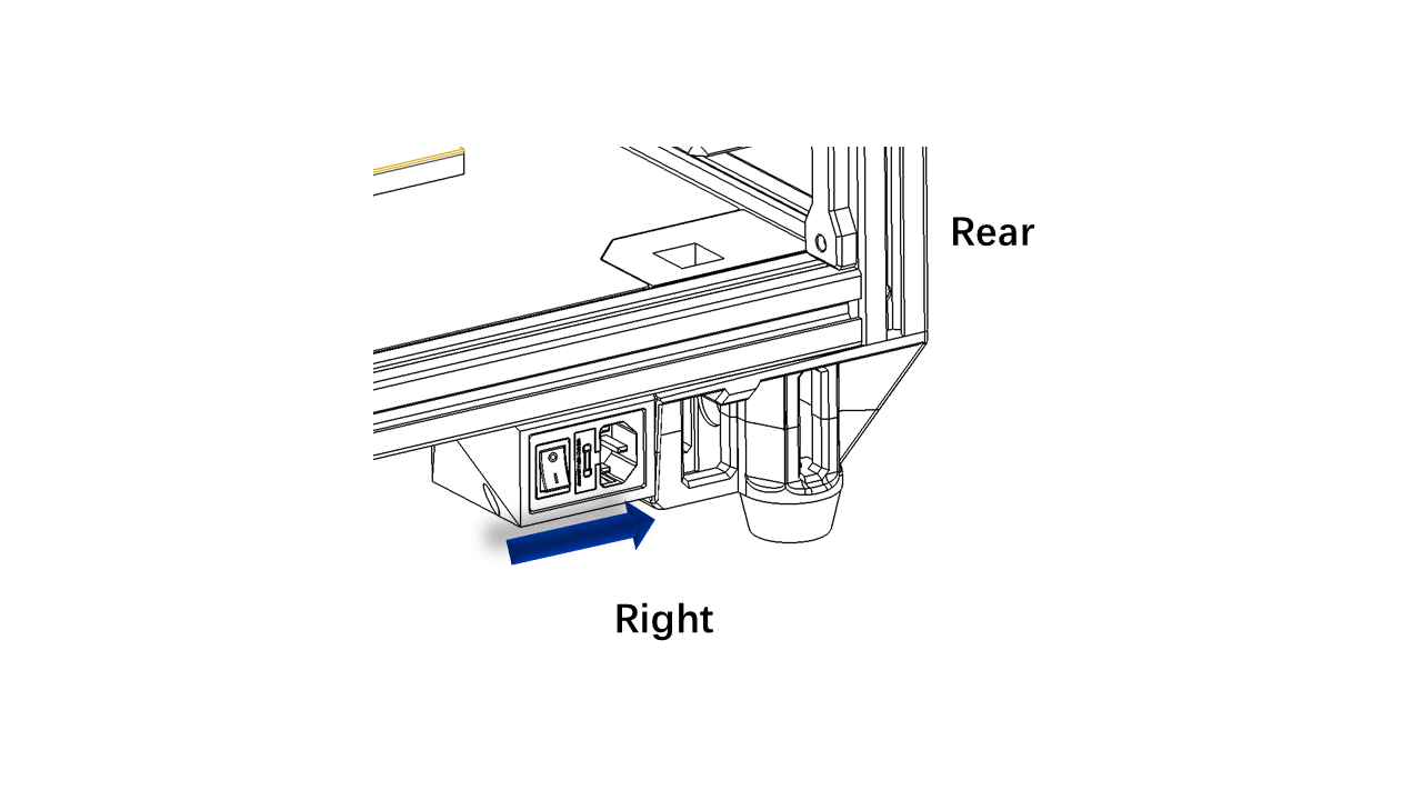
- Fix the power socket on the frame as shown. The power socket should be pushed against the right rear z motor modules.
 .
.
6.3 The electronics
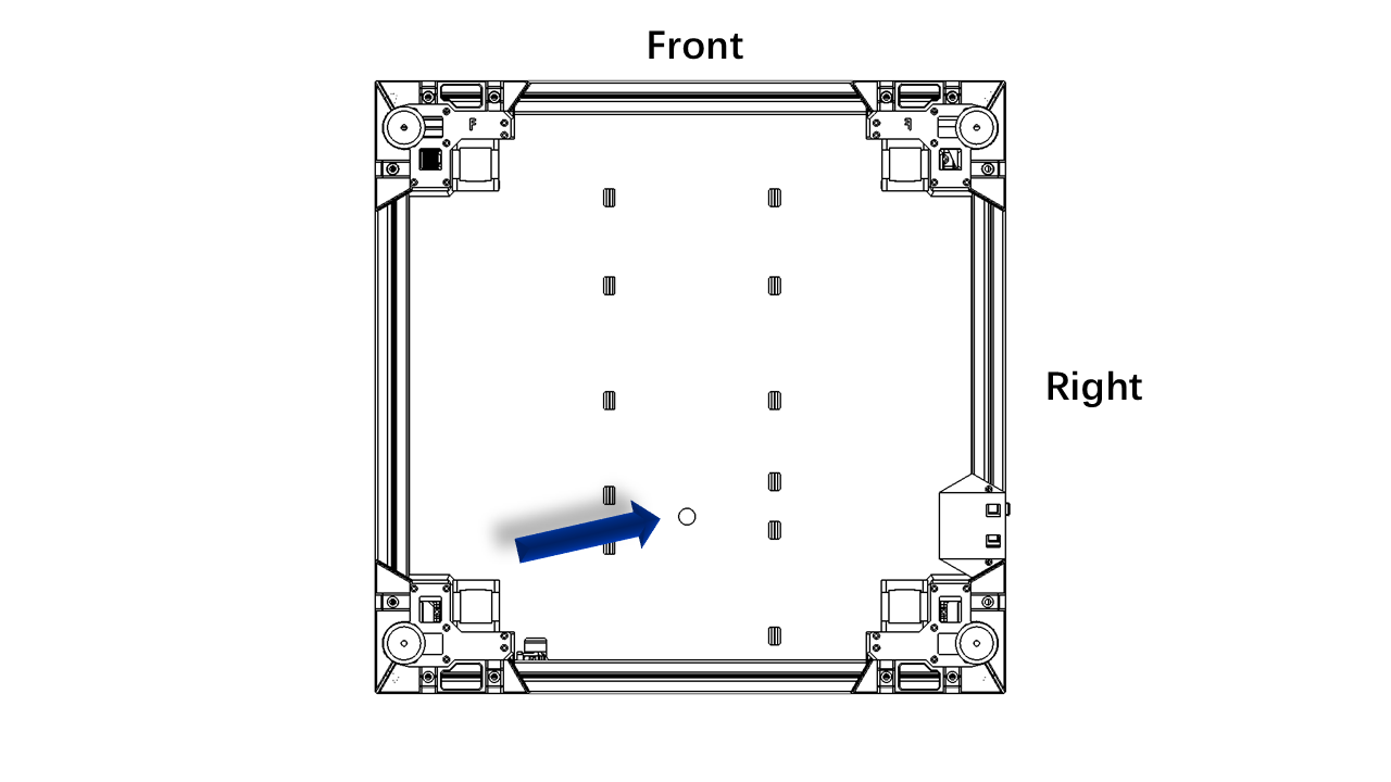
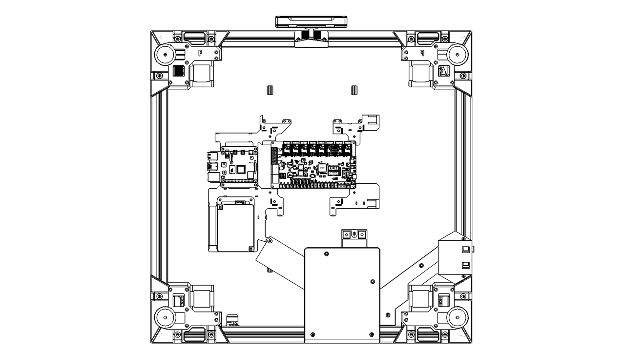
- Now it is time to do the electronics. First, we flip the printer, let the front face upwards.
- Note the round hole location.
.
6.3.0 Install the printed parts
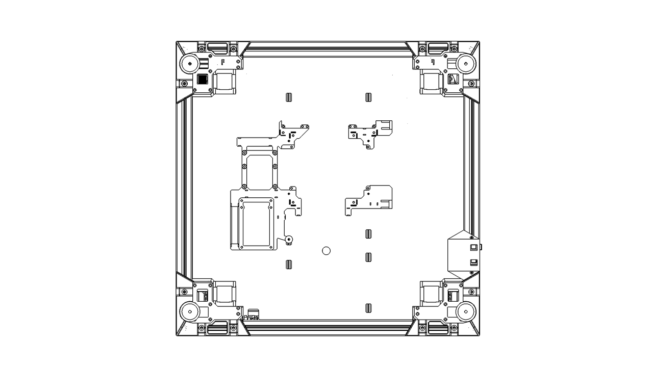
- First, we need to install the support for electronics. Use M3x12 screws and hang the T-nut (2020 M3) on these printed parts. The bottom-most screw should be M3x18.
 .
.
6.3.0 Install the printed parts
- First, we need to install the support for electronics. Use M3x12 screws and hang the T-nut (2020 M3) on these printed parts. The bottom-most screw should be M3x18.
 .
.
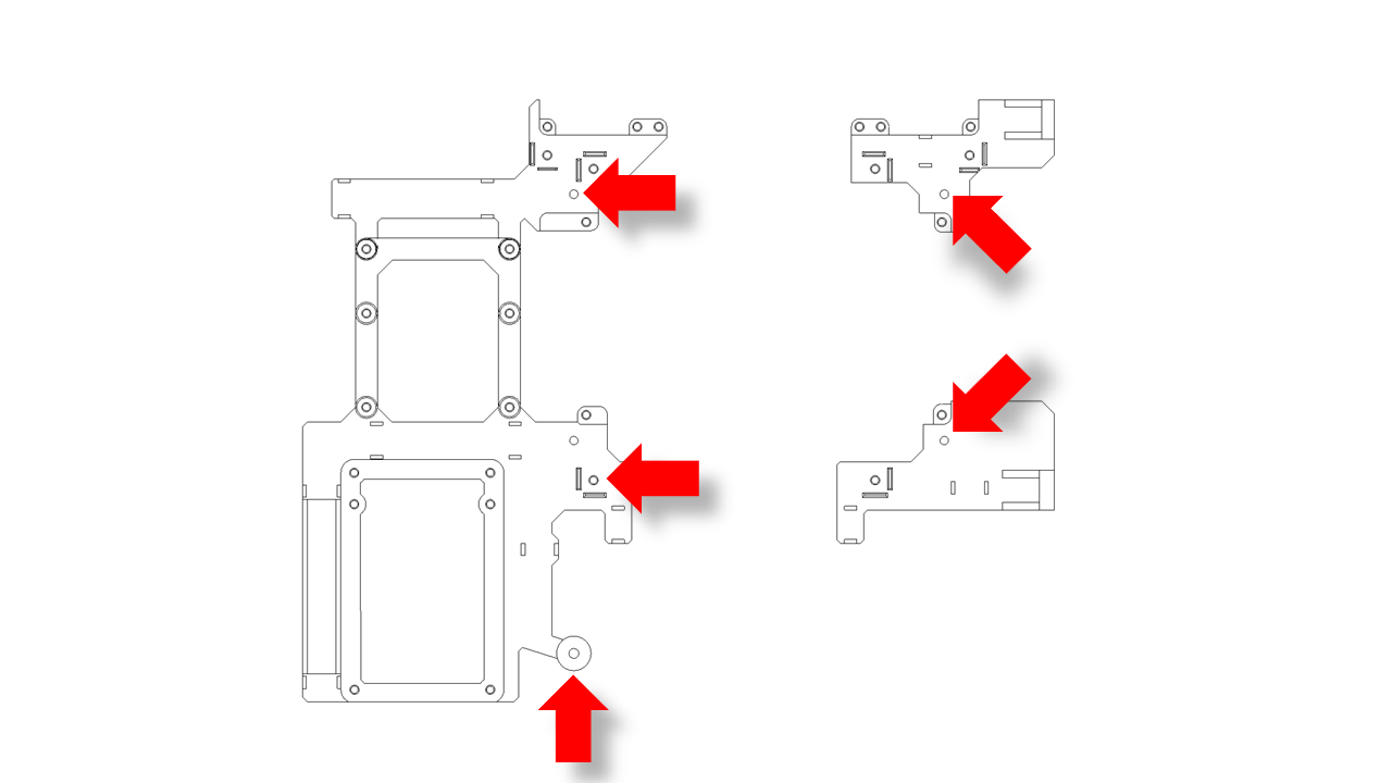
- Install the Control board support, Pi4 support, and ESP32 support in these locations as shown. Do not fully tighten the screws yet.
 .
.
-
Now take the power mount and the SSR mount. Use M3x18 screws and hang the T-nut (2020 M3) on these printed parts. The SSR module should also be included. Note that the 24V side must be facing upward.
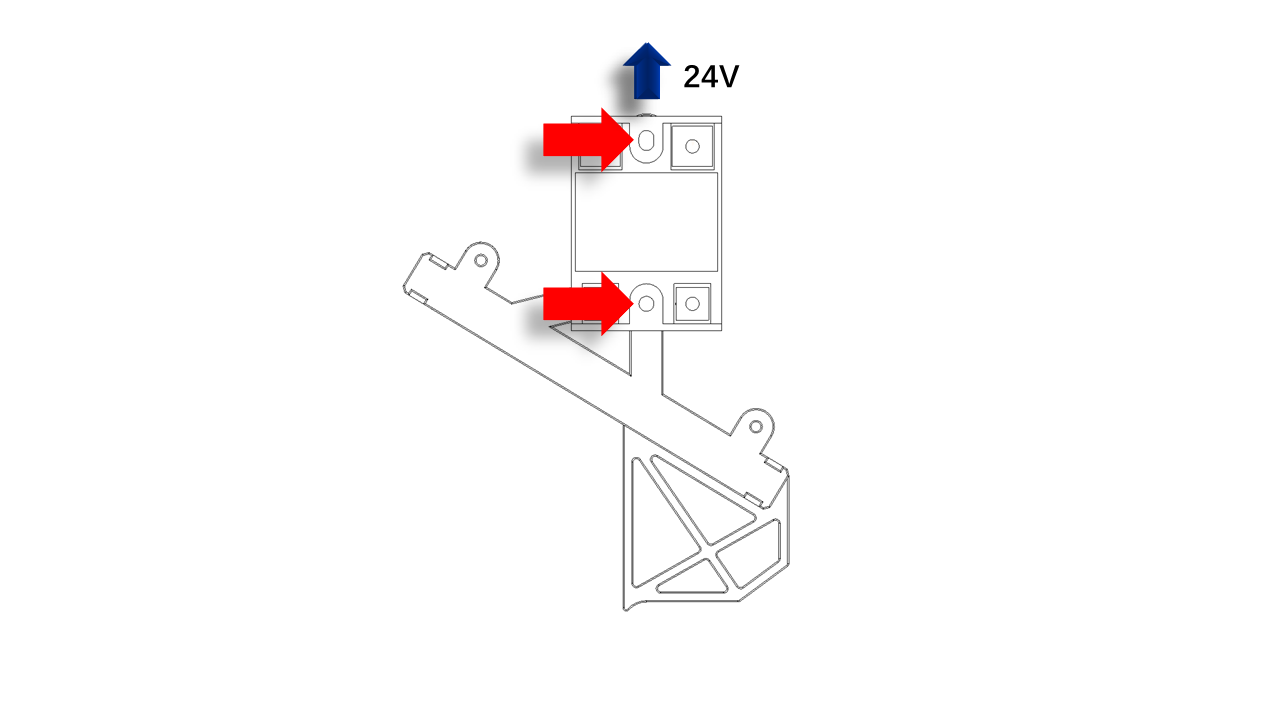 .
. -
Use an M3x12 screw and hang the T-nut (2020 M3). Note the side screw should hangthe T-nut(3030 M3)
 .
.
- Then install the power mount as shown. Note that the printed part also acts as a jig; it should be directly against each other. The power mount should be against the bottom profile. Tighten the screw on the power relay to fix the printed part.
 .
.
6.3.1 Prepare the control board
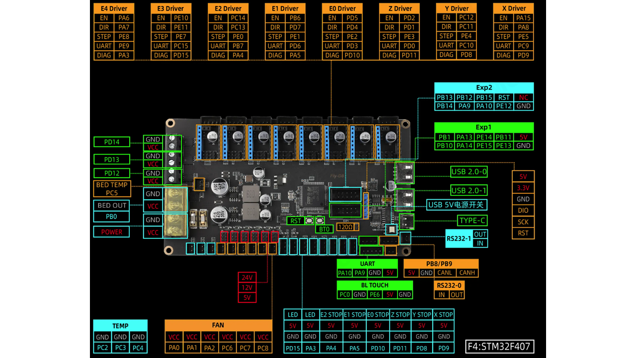
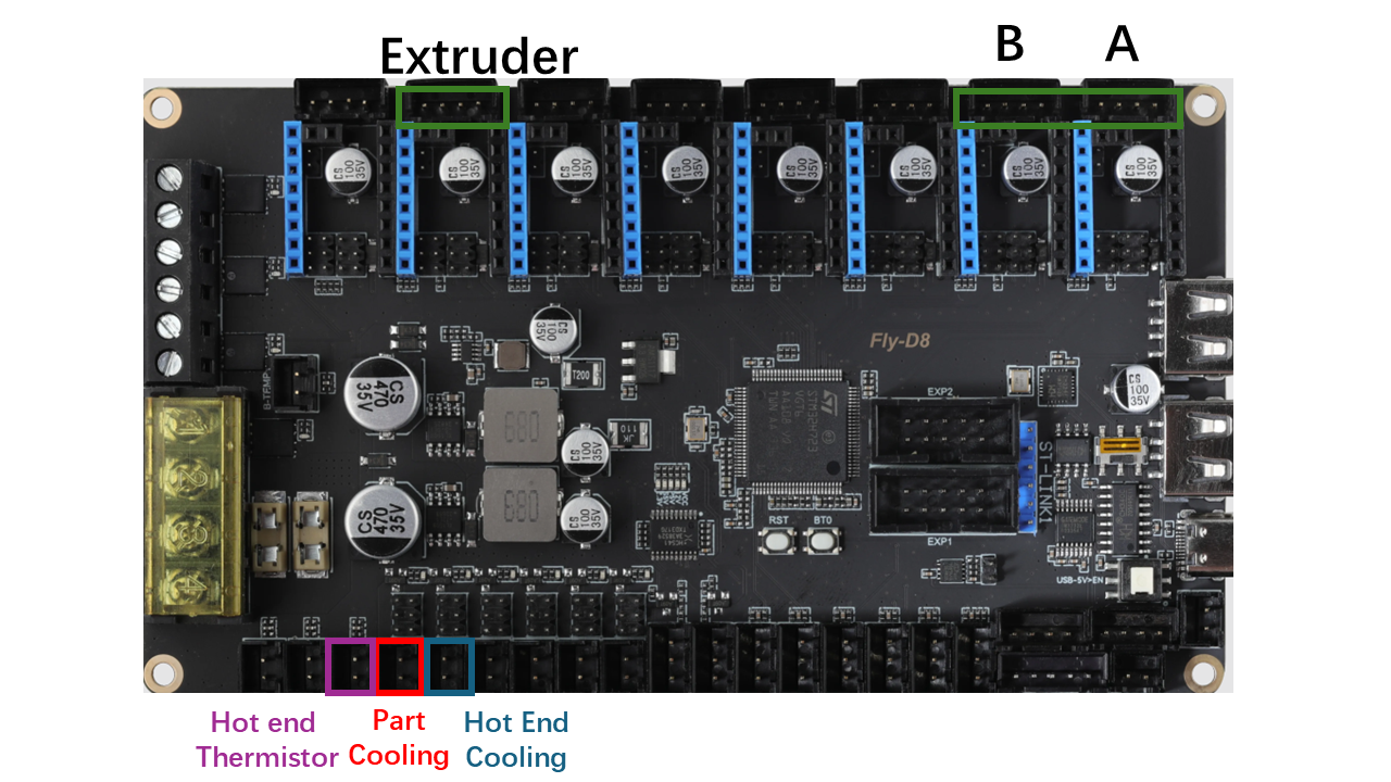
- Before we mount the control board on the printer. We will need to install the motor driver first. In this kit, we use Fly-D8, which has the following config.
 .
.
- Since we usethe TMC2209 driver, we will use the UART mode. Put jumpers on these locations with green marks first.
 .
.
- Then, for X and Y motor,s we need sensorless homing. So we need to install jumpers on these Orange locations.
 .
.
-
Check the jumpers before you install the driver.
-
Then we need to put the jumpers for the fans. We use only 24V fans, so we put jumpers at these locations marked with red marks.
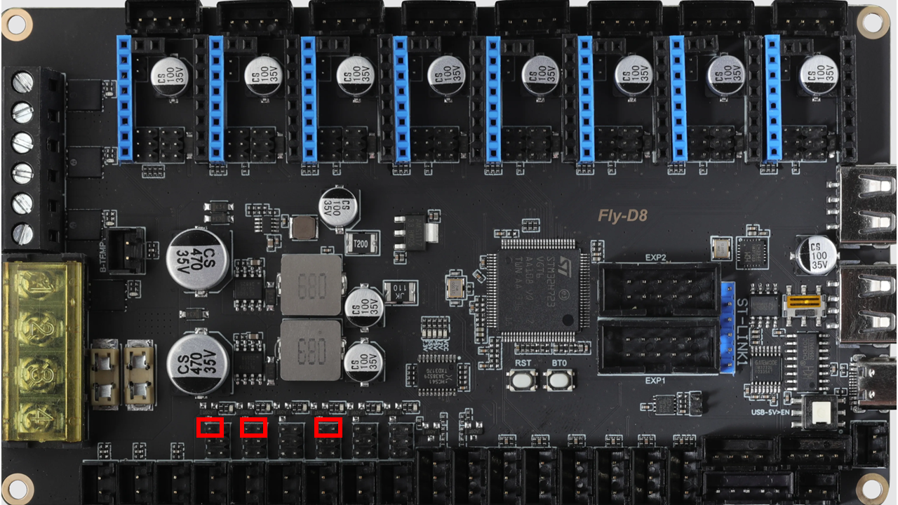 .
.
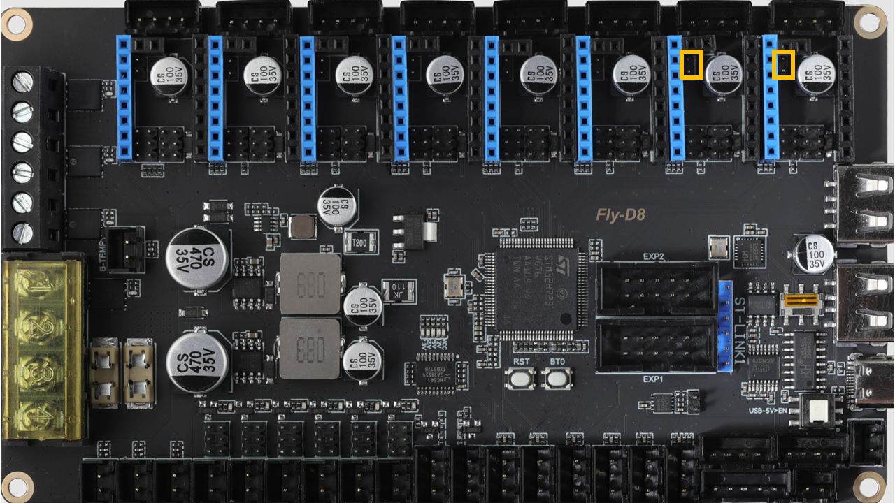
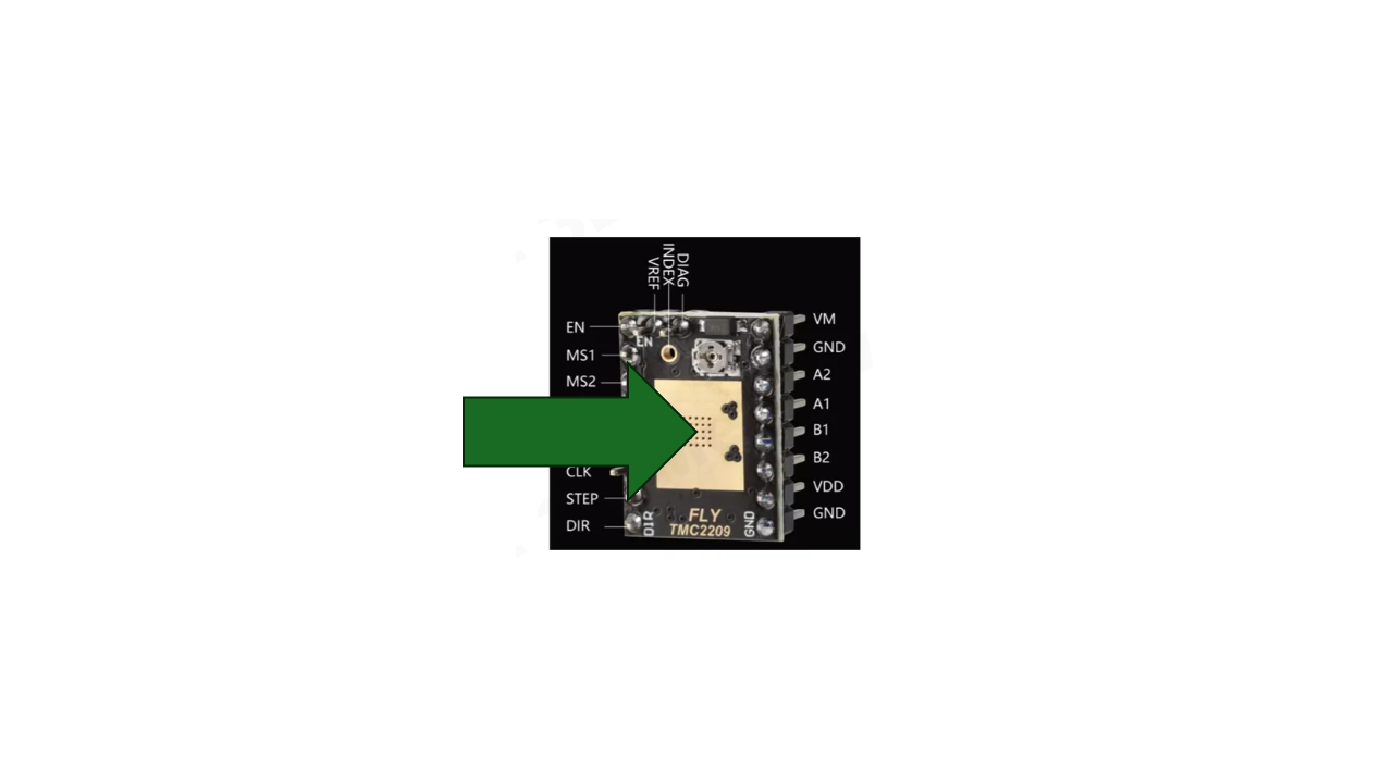
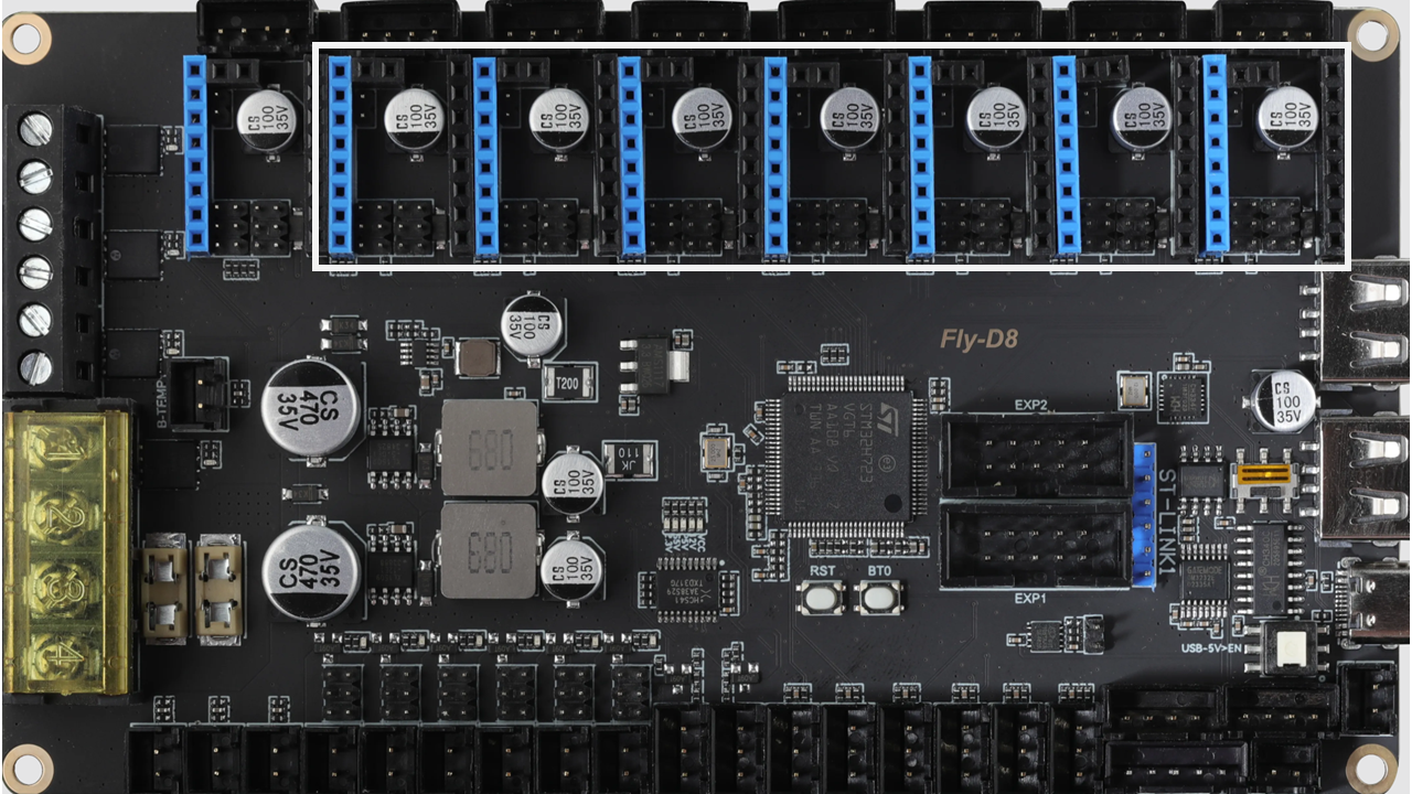
- Then we can now prepare the TMC2209 drivers. There are 7 of them
- Stick the heat sink on the TMC2209 first
 .
.
- Note the orientation. Install the drivers at the locations as shown. The leftmost socket is empty. Note the pin orientation. All pins on the driver should be connected.
 .
.
6.3.2 Mount the control board
- Install the control board on the printed support using M3x6 screws. It should fit just right. If not, slightly loosen the screws and adjust the support.
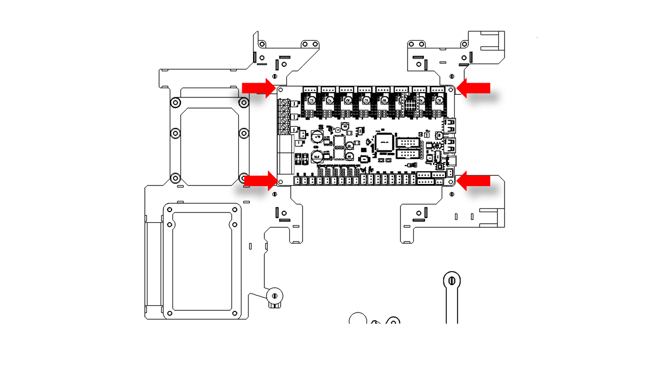 .
.
6.3.3 Prepare the Pi4
- Raspberry Pi 4 is a powerful platform for all sorts of applications. In our kit, it serves as the Klipper Host.
-
The powerful processing capabilities of the Pi4 also enable us to add many other features to the machine in the future.
-
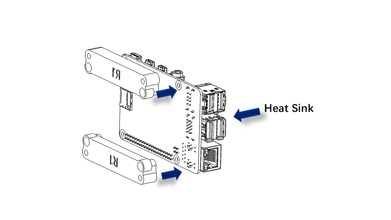
Due to the high performance, it is important to install the heat sink on Pi4. The kit contains ready-to-work heat sinks; we only need the upper half(the side with sockets)
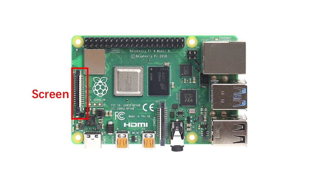
- Connect the FPC/FFC as shown. Note the orientation, the blue stripe should face out of the board.
 .
.
-
Take the Heat sink for Pi and pass the FPC/FFC wires through the notch.
-
Take the Pi mounting support and install the M3x10 screw in these locations.
 .
.
6.3.4 Install the Pi4
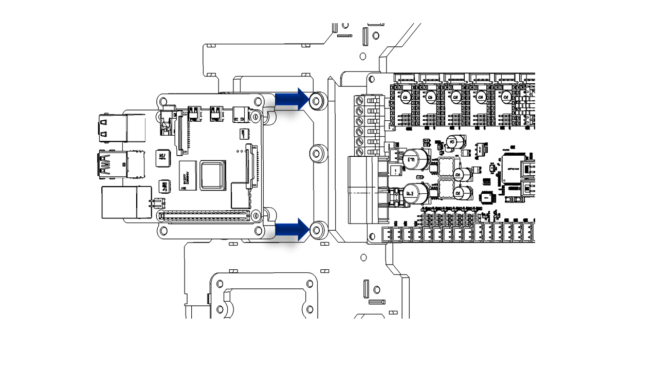
- Use M3x10 screws to install Pi4 here.
 .
.
6.3.5 Install the ESP32
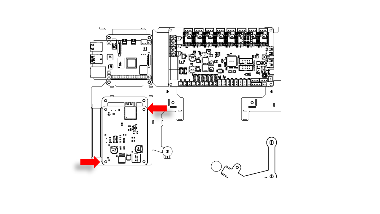
- Use M3x6 screws to install the ESP32. Note that the other two holes are reserved for later use.
 .
.
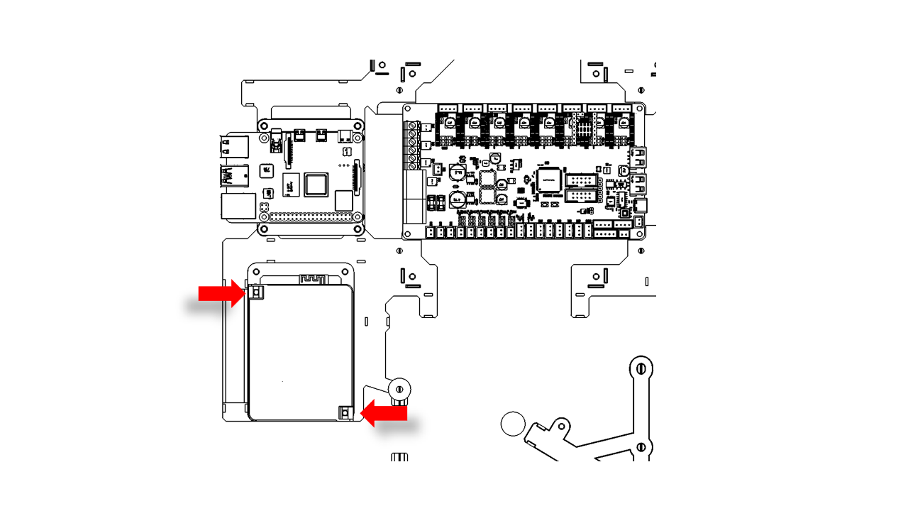
6.3.6 Install the power module
- The power module should be clamped by the two screws as shown. There are notches on the power module that will just fit these two screws, as shown.
 .
.
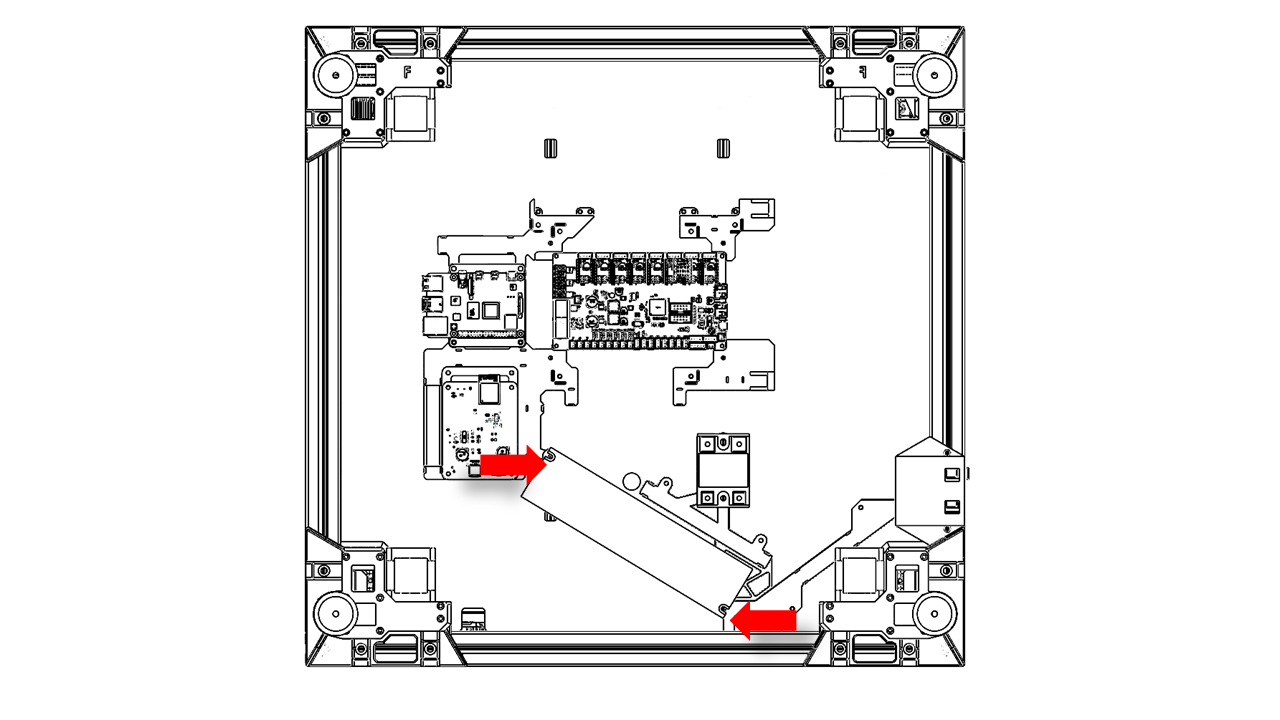
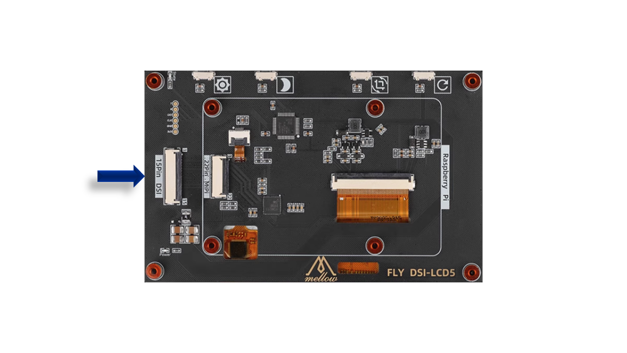
6.4 Assemble the screen
- Connect the screen wire.
 .
.
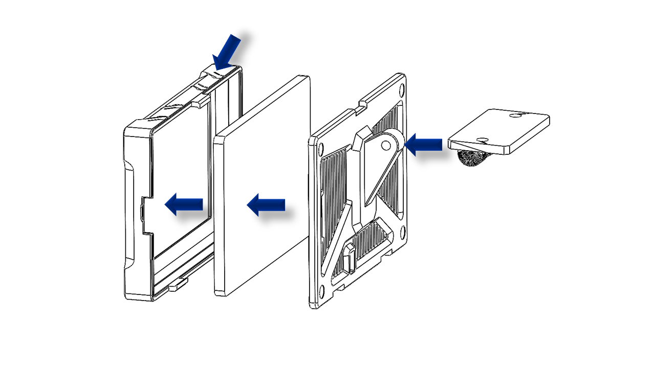
- Take the screen cover and insert the 5 inch LCD screen. Note the screen has buttons; they should fit the printed press buttons. Then take the back panel and cover the screen.
 .
.
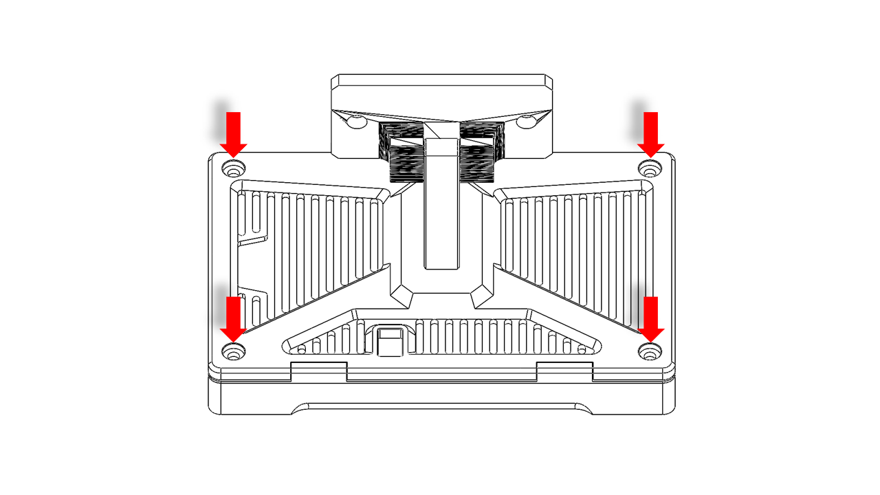
- Use M2 x 6 screws to fix the back panel.
 .
.
- Use an M5 x 25 screw as a pivot, and use an M5 nylon nut on the other side to fix the screw.
- Do not fully tighten the screw. Make sure you can move the screen mount.
- Insert M5 x 10 screws in the screen mount and hang the T-nut (M5 3030).
 .
.
- Fix the screen mount on the bottom frame as shown. Adjust the screen so that it is in the middle.
 .
.
6.5 Wiring
-
For P350, we use Fly-D8 as the control board. You can check their official website if you need to DIY
-
For our kit, please follow the instructions below:
6.5.0 Z Motor wires
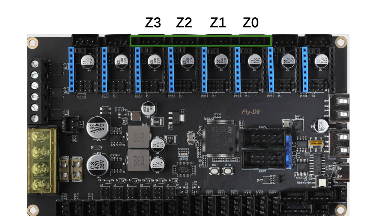
- Connect motor wires on Z motors. Note that we will need to connect the Z motors in order.
 .
.
6.5.1 Heated Bed wires
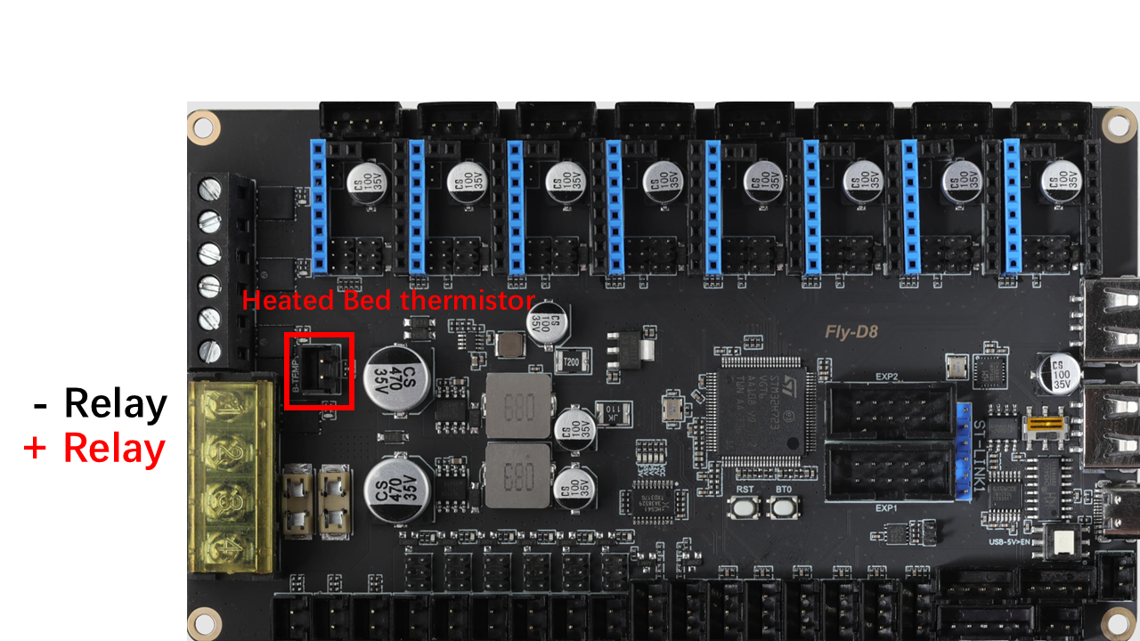
- Collect the heated bed wires we inserted in section 4. Connect the Heated bed wires as shown
 .
.
6.5.2 Tool head and Gantry wires
- Collect the tool head wires from the square hole and connect them as shown.
 .
.
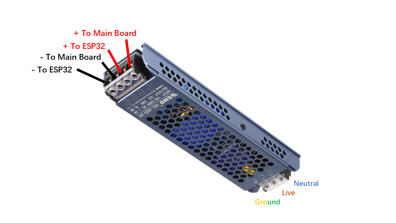
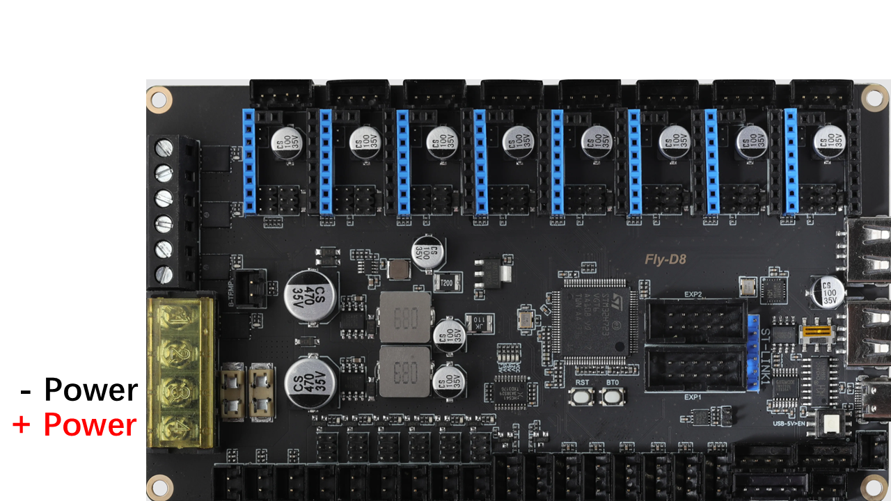
6.5.3 Power wires
- Connect the power wires from the socket as shown.
 .
.
- Then connect the power wires as shown.
 .
.
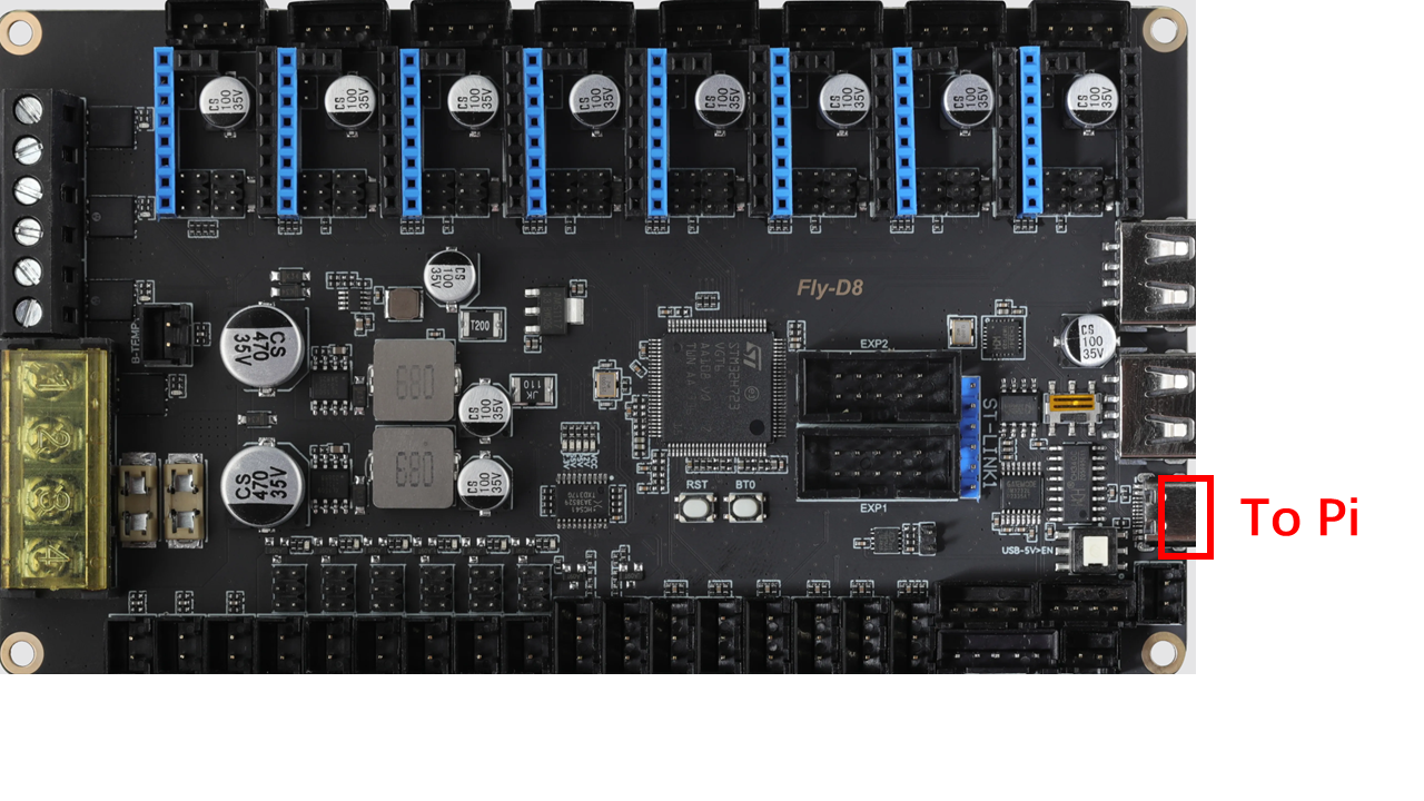
6.5.4 Pi4 wires
- Take a USB Type-C and connect to the location shown.
 .
.
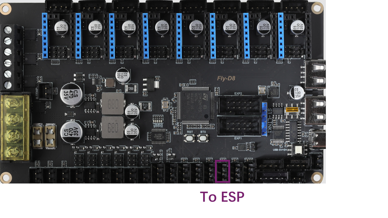
6.5.5 ESP32 Wires
- Take the yellow-black wire. Connect the wire to the main board as shown.
 .
.
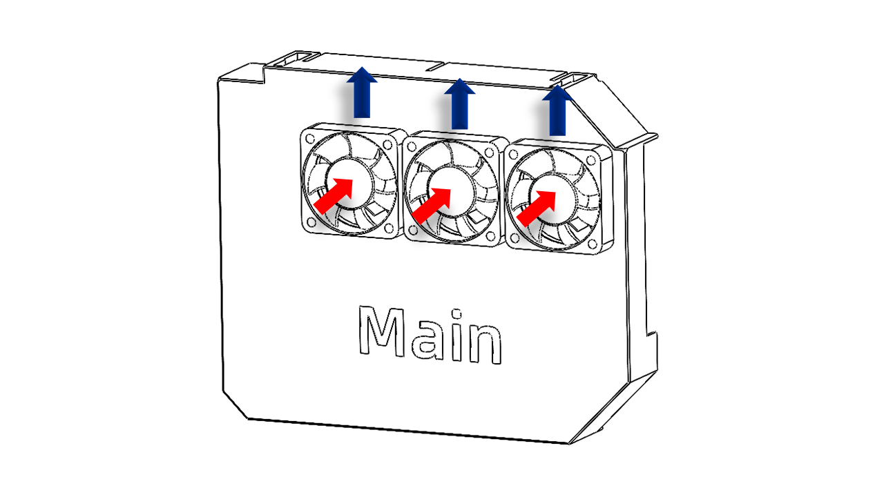
6.5.6 Electronic cooling Fan wires
- Note that motor drivers require active cooling. So we have to install fans. Use M3x12 screws to install the 4010 fans (with short wires) on the Main cover as shown. Note the fan wires go upward.
 .
.
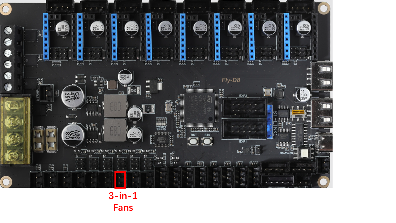
- Connect these fans with a 3-in-1 adapter
- Connect the adapter as shown
 .
.
6.5.7 Check and sort the wires
- Please check the wire config and make sure it is correct. Especially the high voltage part!
- Then you should use ziptile to sort and fix the wires. There are many ziptile locations for you to use on the printed parts. They look like this:
 .
.
6.5.8 Install cover
- Install the power wire cover with M3x12 screws as shown; this should hide all high-voltage wires from the socket to the power module.
 .
.
- Use M3x 16 screws and hang the T--Nut(3030 M3) on it.
 .
.
- Install the power module cover as shown. Use M3x12 screws to fix the cover on the printed support.
 .
.
- Install the ESP cover as shown. Use M3x12 screws
 .
.
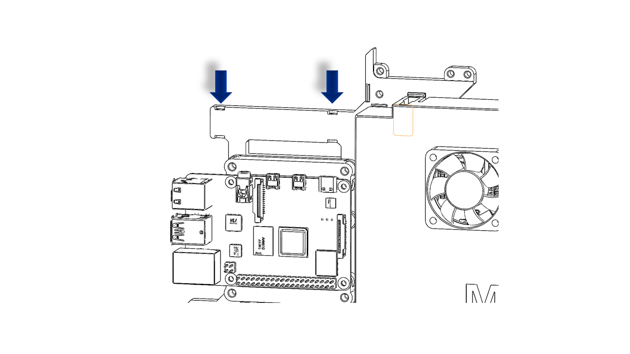
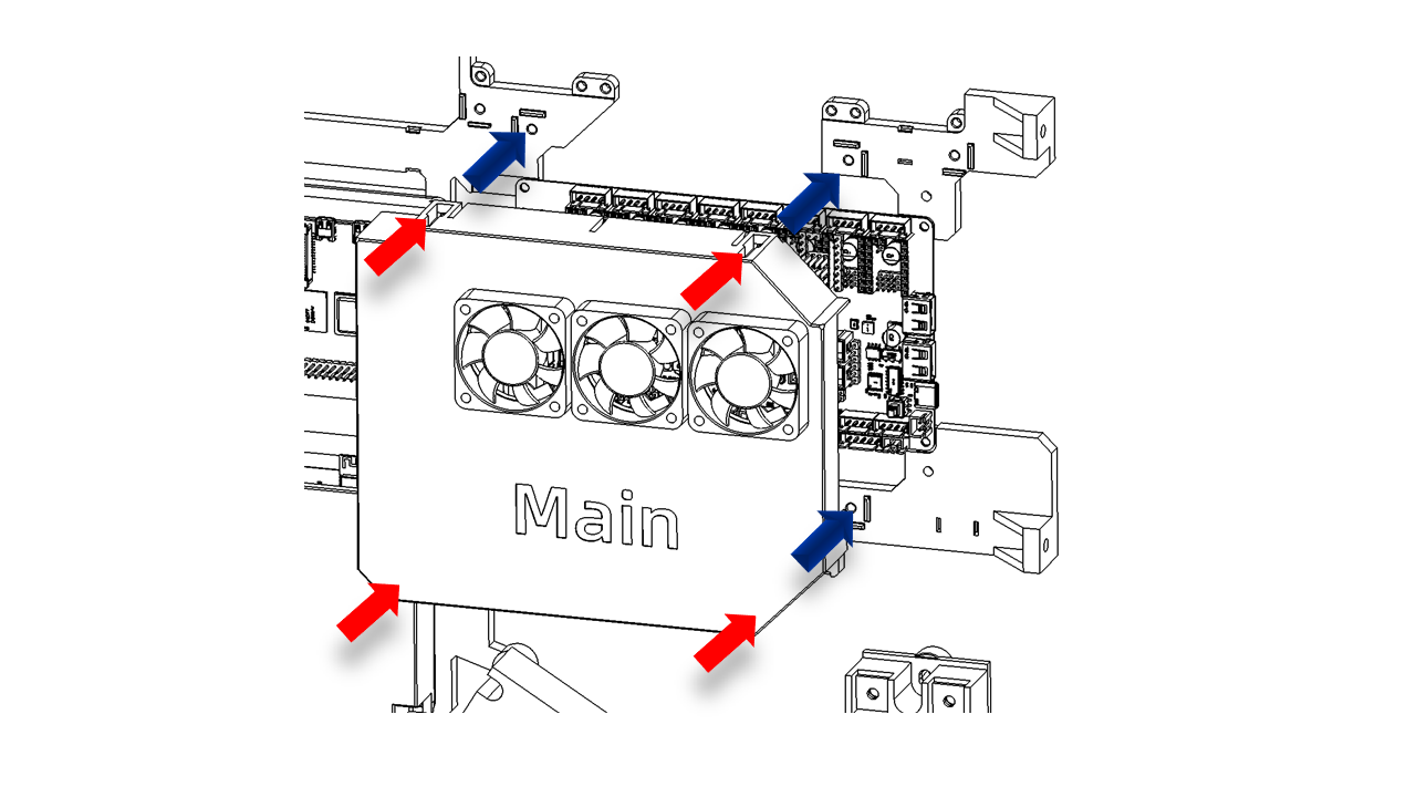
- Finally Install the Main cover with fans using M3x6 screws. The main cover should fit the slots on the electronic support. The gap on top is for the screen wire.
 .
.
- The final result should look like this.
 .
.
7.Firmware
- Now we can flash the Firmware.
7.1 The Pi4
-
Download the System image via the following link: ()
-
Take the SD card and follow the instructions on the Raspberry Pi official website(link) and flash the System image we just downloaded.
7.2 The Fly-D8
-
Download the System image via the following link: ()
-
Follow the instructions via this link to flash the image to your SD card:Link
7.3 Printer configuration
- We recommend you copy and paste the default printer configuration first. To get the configuration, please click here: (git链接)