Stage 2:Frame Upgrades & Dual Belt Plus
1. Preparation
1.0 Introduction
READ THE INSTRUCTION BEFORE UPGRADE!!
-
Since you are upgrading an existing Original Prusa or clone, if you have experience in assembling Original i3, that’s perfect! if not, don’t worry, follow this guide, everything will be smooth and fine. Also feel free to contact us.
-
Disclaimer: We share these guides to make your experience as smooth as possible. However, you are responsible for your upgrade, assembly, and any damage you cause to your hardware.
1.1 Check before Upgrade
Make sure you have the following tools and things available:
-
Your Original i3
-
4mm, 3mm, 2.5mm, 2mm, and 1.5mm hex keys for disassembly, you can find one 1.5mm hex key in our accessory pack if you do not have one.
-
A cutting tool for cutting zip ties
-
Your Prorifi3D upgrade kit
-
A box for keeping the screws
-
Printed parts from our GitHub
-
Open the Original Prusa i3 MK3S kit assembly Guide for reference(https://help.prusa3d.com/en/guide/1-introduction_24976)
-
Make sure you have a flat surface such as a polished marble top, or a big ceramic tile. This surface will be your base level.
-
Make sure the filament is unloaded before the upgrade. You will have to turn the printer over during the process so the filament spool and spool holder need to be removed before the upgrade.
-
Make sure your printer is Not powered, the nozzle and heated bed are fully cooled to room temperature! Otherwise, you may injure yourself!
-
Make sure both ends of the power cord is unplugged to allow the printer to be placed sidewise.
-
For disassembling the Original i3 you can refer to this guide:https://guides.bear-lab.com/Guide/02.+Preflight+check+and+disassembly/42?lang=en
-
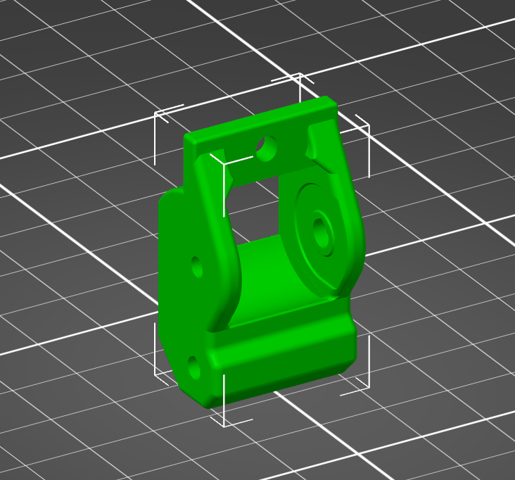
For the Dual Belt Plus please use PETG with at least 30% infill. The printed part should orientate as shown. Note that this part can be printed without support.
2. Assemble the Main Frame
2.0 Check before the assembly
-
Make sure you have the following parts: All the aluminum profiles, your Hex Keys, Accessory Pack 1
-
A measuring tool for screws, you can find the STL file here (If you know how to measure the screws then use a ruler instead)
-
Make sure you have a flat and big enough surface such as a polished marble top, or a big ceramic tile. This surface must be able to fit the longest Aluminum profile in any direction. Clean the surface to remove any dust or small debris.
-
Check the inside of the two longest beams, there should be two plastic plugs been pre-installed at both ends. If not, please contact us.
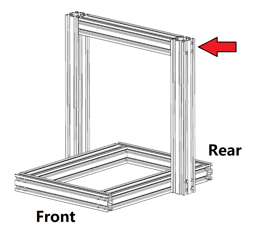
2.1 Assemble the gantry
-
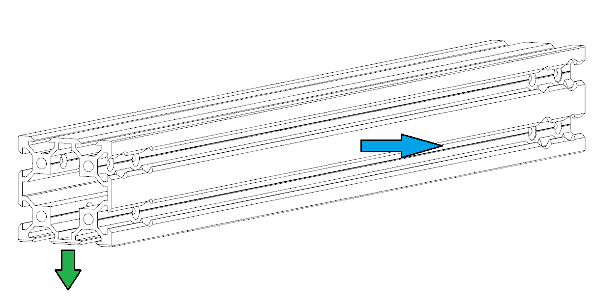
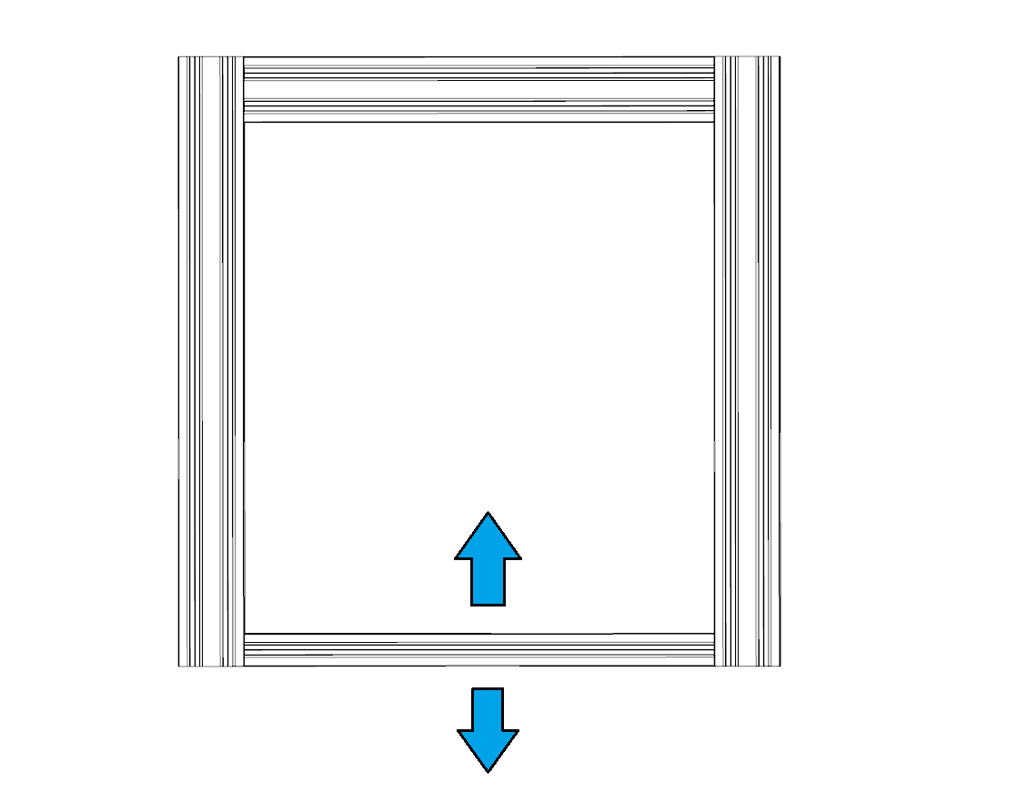
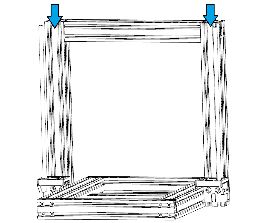
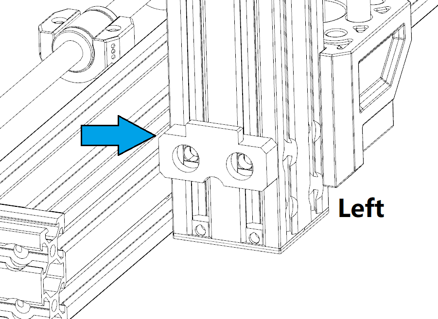
Take the left and right vertical beams (the longest ones).
-
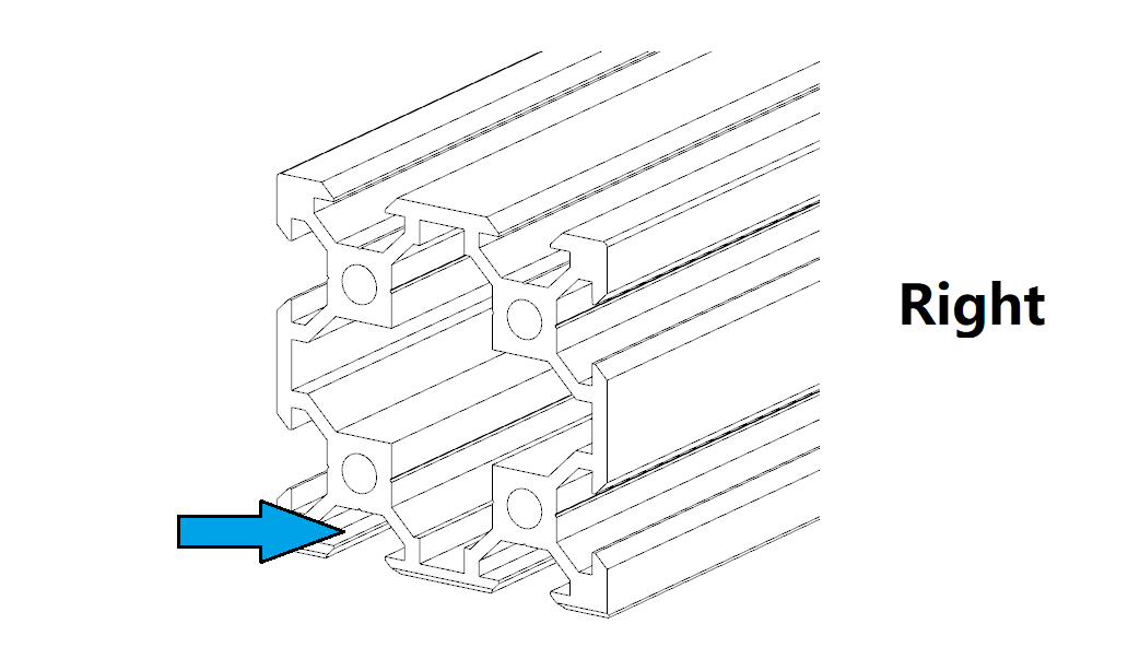
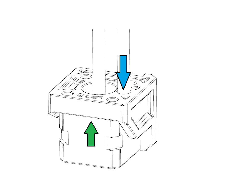
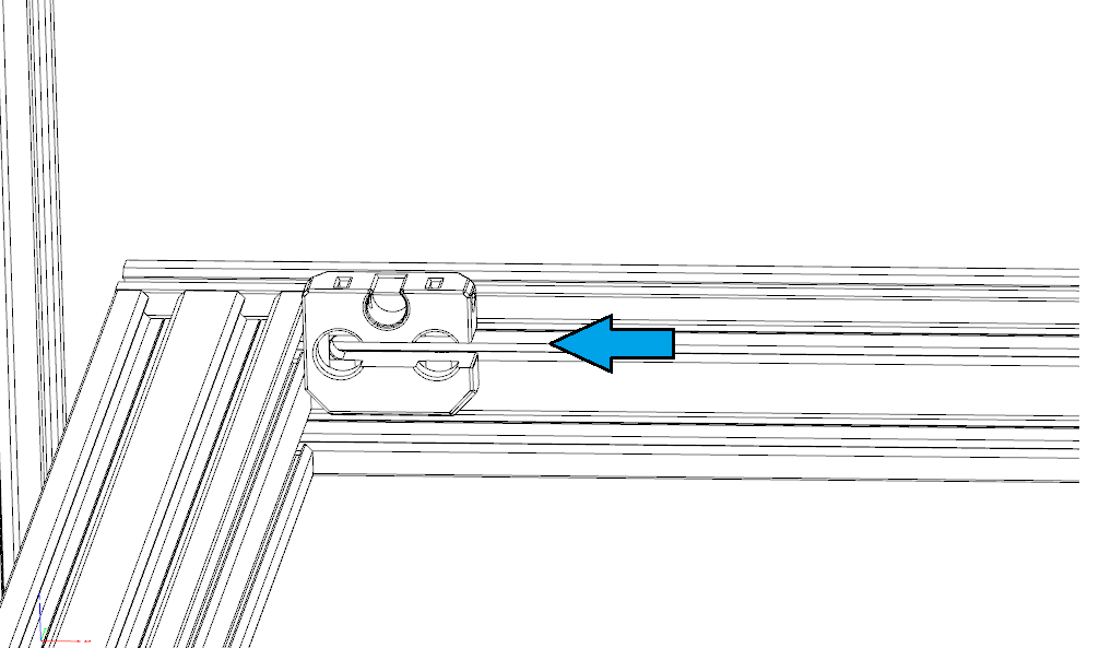
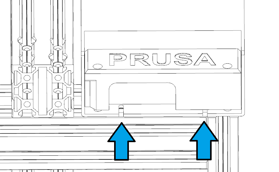
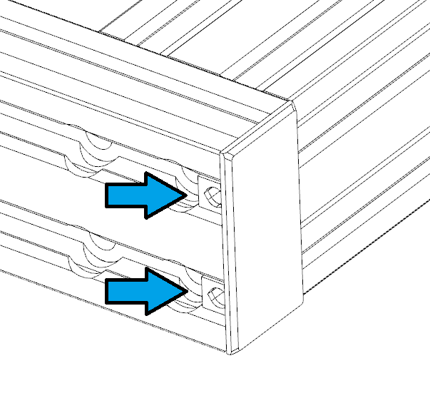
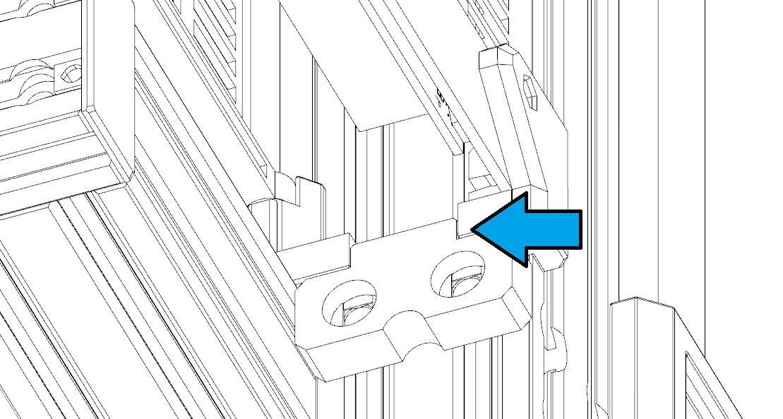
Check the beam and make sure you have the correct orientation. The side with chamfers should face downward, against the flat surface. The side indicated by the blue arrow should face outward.
-
Take the short 4040 profile and place them as shown. The side with Chamfers needs to be facing down, against the flat surface.
-
Use one 2040 beam as the jig, place it as shown
-
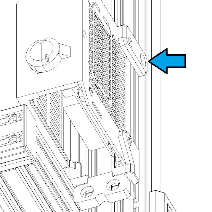
Note the orientation! The 4040 should on the side with 3 screw holes.
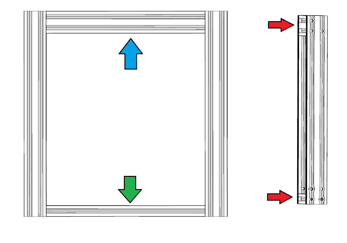
- Use M5x45 screws from Accessory Pack 1 and tighten the screws as shown on both sides. Note the Upper one is for adjustments. Do not fully tighten it.
- Adjust the upper screws on both sides evenly to make sure the 2040 beam used as a jig can just about move freely up and down at the open end of the gantry
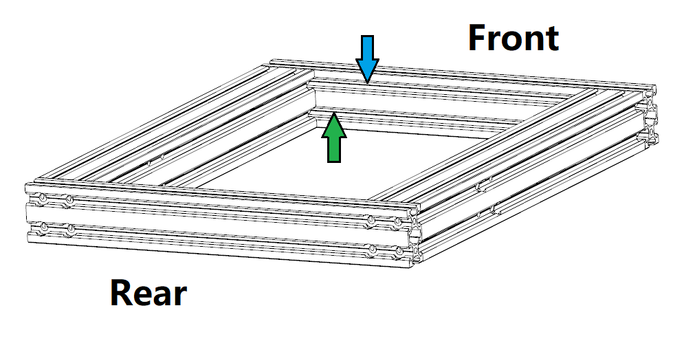
2.2 Assemble the base
-
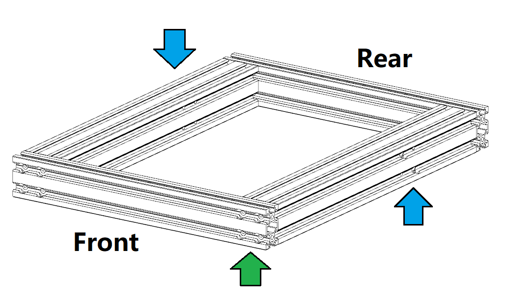
Take the rest 4040 and 2040 profiles
-
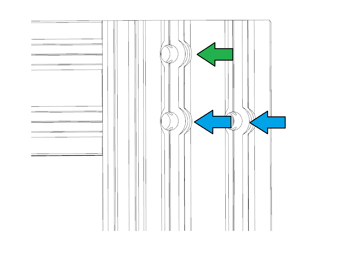
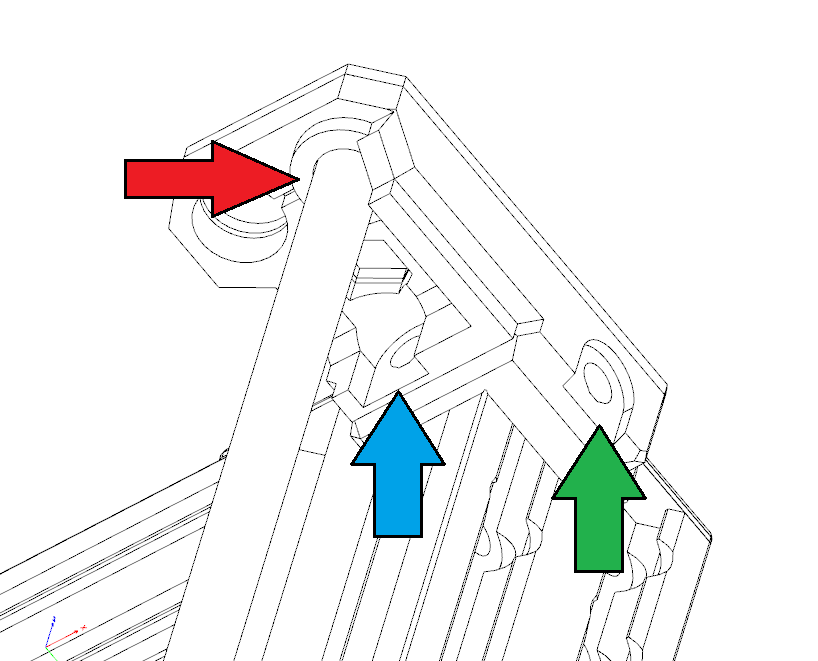
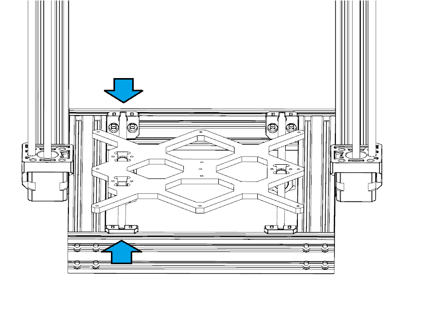
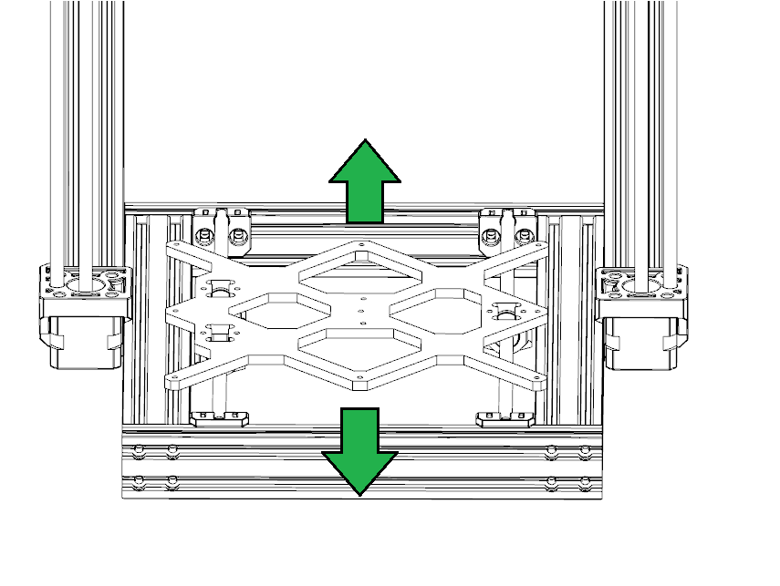
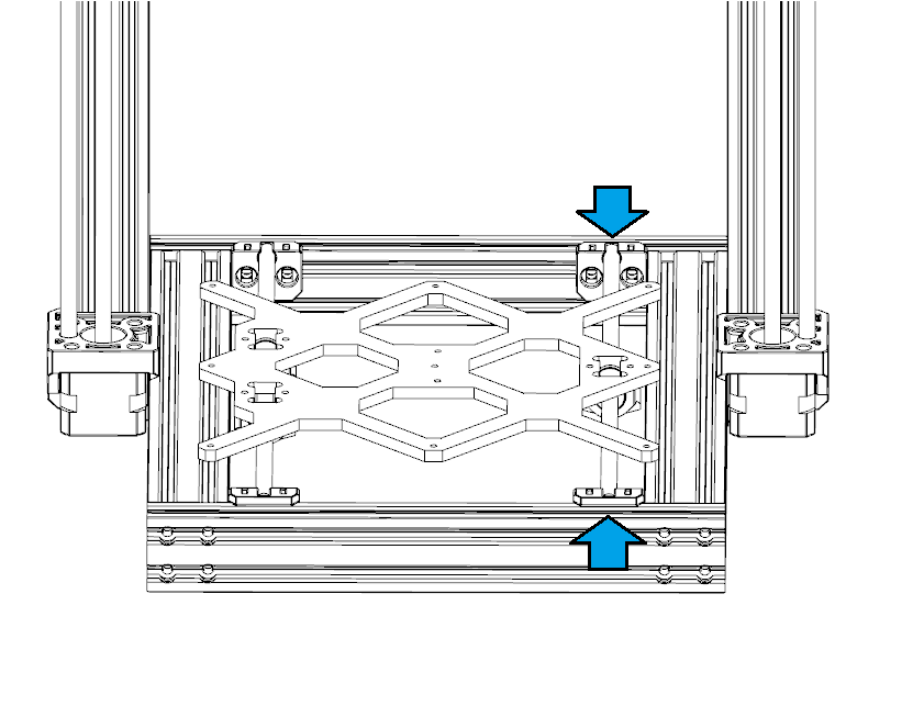
Check the beam and make sure you have the correct orientation. The side with chamfers needs to be facing down, against the flat surface. The sinkholes should face out as the green arrow shows. The front and rear 2040 profiles are the same, just make sure you have the correct side facing out and chamfered side facing down.
-
Place them as shown. Note that for the 4040 profiles, be careful with the position of the screw holes. Make sure you have the correct relative position!
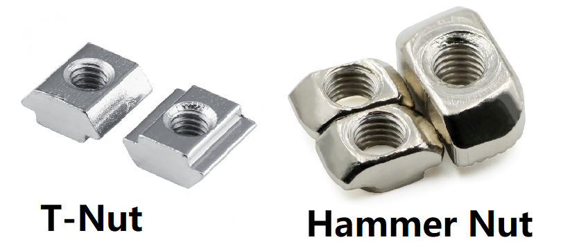
- Insert 2 T-Nut in the bottom inner slot of the 4040 profile, do this for both left and right 4040 profiles. These will be used to fix the footpad later.
- Insert 6 T-nut in the upper slot of the inner side of the rear 2040 profile and insert 1 in the lower slot.
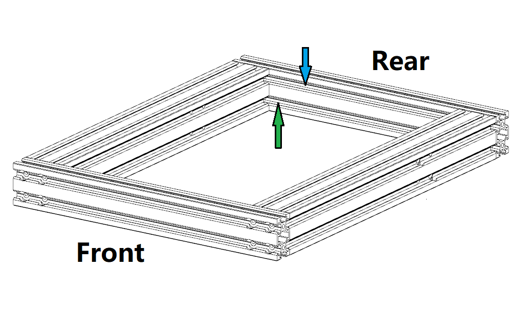
- Insert 6 T-nut in the upper slot of the inner side of the front 2040 profile and insert 2 in the lower slot.
-
Double-check if you insert the correct amount of T-nuts and they are in the correct position!
-
Now we can build the base. Make sure both sides are aligned. You can use a piece of a flat surface, such as the jigs you printed to help you align these beams.
-
Take the M5x25 screws, you need 16 of them. Use them to fix the front and rear profiles. Make sure you tighten them in a diagonal order. When tightening the screws, do not fully tighten a screw before you tighten the next one. Screw them in evenly. Make sure all the aluminum profiles are not moved or have gaps with the flat surface. This is very important!
-
Turn the base over and install the footpad. Use M5x10 button head screws to fix them. Turn the base back and if it shakes, adjust the screws on footpads until they are all in the same plane.
2.3 Assemble the mainframe
-
Check if the T-nuts are correctly inserted again before this part!
-
Make sure the reference surface (the side with chamfers) for the base is facing downwards, against the flat surface. At this point, the reference surface should be flat and directly touching the flat surface with no gaps between.
-
Take the gantry, make sure you have the correct orientation!
-
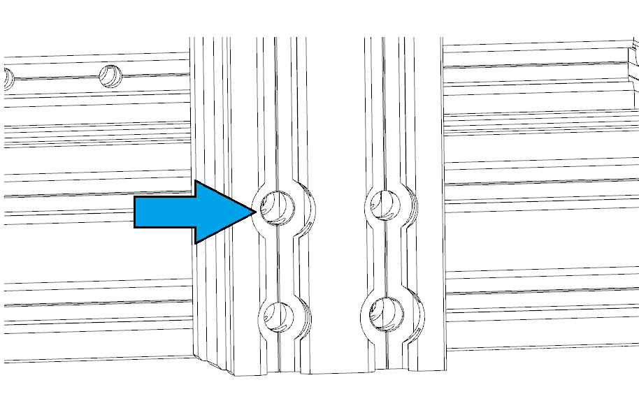
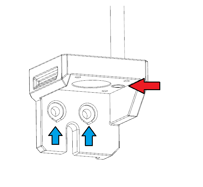
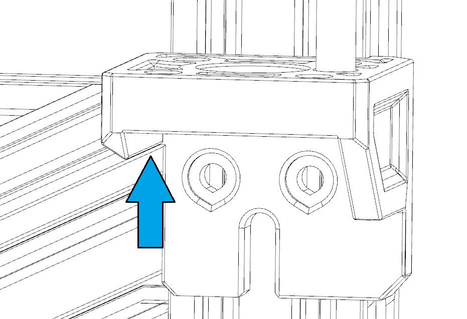
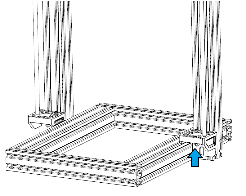
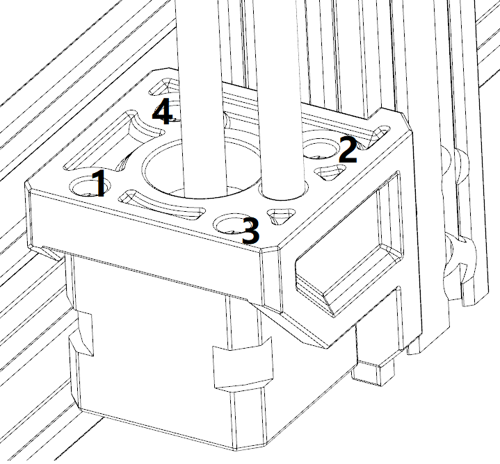
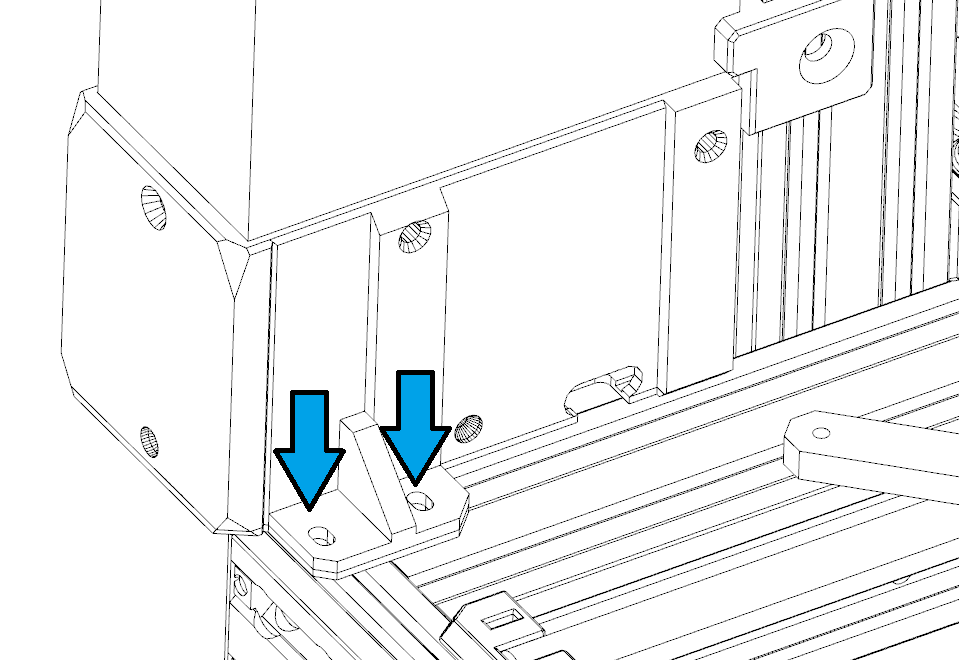
As you can see, on the lower end of the gantry there are 4 screw holes on each side, and they are shaped differently. Viewed from one side, the upper left one is the pinhole. And the 4 screw holes match the holes on the base.
-
Carefully match the gantry and the base. Take a shoulder screw(the one with steel case) and insert it into the upper left pinhole to the bottom, slightly tighten this screw. It is ok if you feel some force or resistance when inserting this screw.
-
Do the same for the other side. Now the position of the base and gantry are locked and make sure the gantry stands against the flat surface, there should be no gap between the gantry end and the surface, or the base and surface.
-
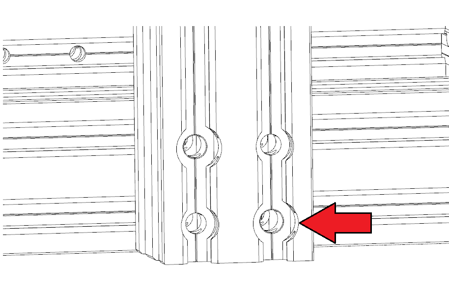
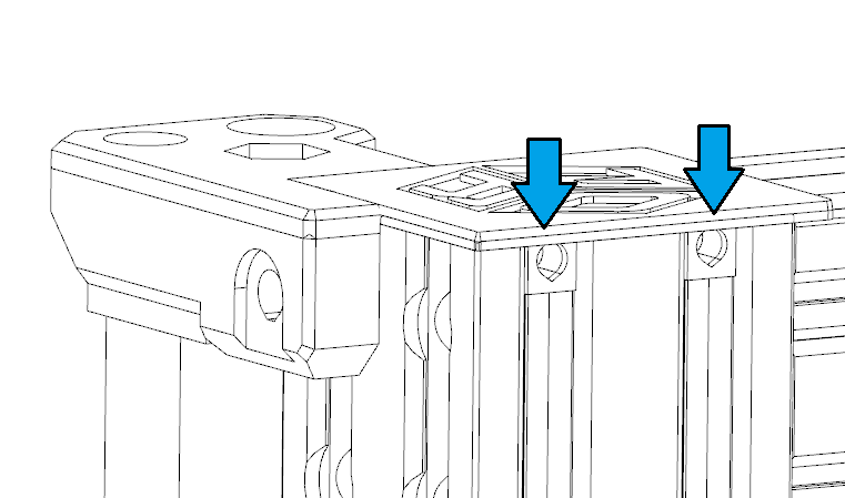
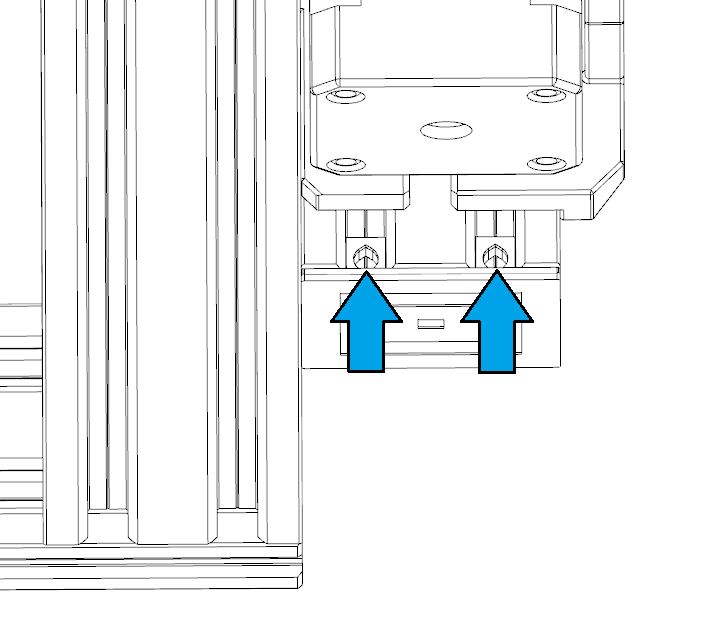
Now the gantry is perpendicular to the base, take the M5x70 screw (the longest normal screw) and install them to the lower right hole on each side.
-
Take 4 M5x50 screws to fill the rest screw holes.
-
Now you should tighten the screws evenly in a diagonal order. Note that the shoulder screw is for positioning thus cannot be tightened much. Make sure the rest M5 screws are fully tightened!
-
The main frame is now finished, if perfectly assembled you should see no gap between the base and the flat surface you have. And if you shake the gantry, there should be absolutely no relative movement between the gantry and the base.
2.4 Prepare the next phase
-
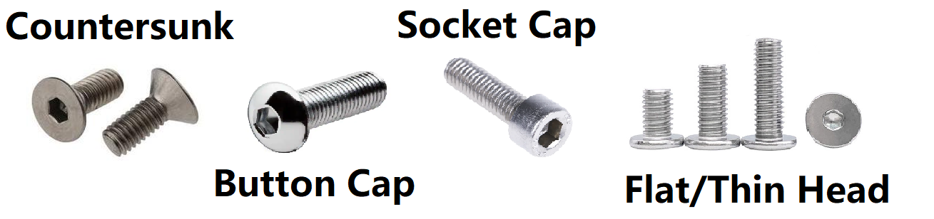
At this point, we just finished the main frame and are moving to the next phase. It is time to take the accessory pack 2. There are many screws in it so be careful. You will find screws with the socket head cap, the button head cap, the flat head cap, and the countersunk screws. You can use the measuring tool to help you classify the screw.
-
If you found anything confusing or are not sure, you can always reach out to us!
3. Disassemble your Original i3
3.1 Modifications before disassembly
-
Before you do the disassemble. Please change the X motor first as we will reuse the entire X-axis and E-axis later.
-
If you would like to replace the E motor as well, please refer to the section: 5. E-axis assembly in the offical guide to rebuild the E axis with the Prorifi3D E motor.
3.2 Replace the X motor on the X-axis
-
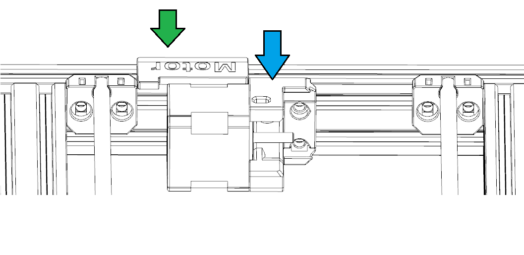
Untighten the screws on the driving pulley to make sure you can remove the pulley from the motor later. There are two screws 90 degrees apart on the pulley.
-
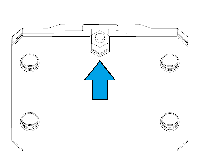
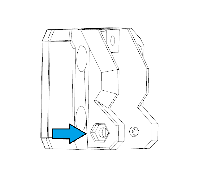
Slowly push the E axis away from the X motor side. Use the finger to snap the belt. You should feel some force which means the belt is tight. Now slowly untighten the tension screw and the three screws that fix the X motor with a 2.5mm Allen key until you feel no force between your fingers.
-
Now use your hand to assist and hold the X motor so it will not suddenly fall off. Use a 2.5mm Allen key to remove the three screw that holds the X motor. Do not keep the screws.
-
Take off the X motor and remove the pulley from the motor.
-
Put the motor aside. keep the driving pulley in the box for later use. Leave the belt hanging for now.
-
Cut the zip tile on the sleeve, and remove and keep the sleeve for later use.
-
Put the sleeve on the Prorifi3D X motor wire just like you did for the original motor. Use a zip tile to secure the sleeve position
-
Install the Prorifi3D X motor in the original position, make sure you use M3x16mm screws.
-
Reinstall the X driving pulley
-
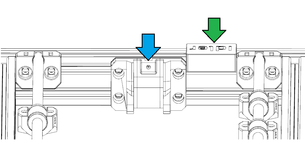
Adjust the position of the X driving pulley, make sure the belt does not touch the edge of the pulley when moving.
-
Adjust the tightness of the X belt. We can fine-tune the belt tension later according to the print test.
3.3 Disassemble
-
For disassembling the Original i3 you can refer to the bear guide:https://guides.bear-lab.com/Guide/02.+Preflight+check+and+disassembly/42?lang=en
-
The Bear upgrade is also a decent frame upgrade and we took some inspiration from it despite using a completely different approach and mechanical design principles.
-
The part you need to keep and reuse later:
-
The entire X-axis and E-axis together
-
The PSU
-
The Y-axis, including the rod, but without the belt system
-
The Control board and the control box
-
The Z rods
-
The Z motors, if you did not get the full upgrade kit
-
The LCD
-
The Control Box
-
4. Build the Machine
4.0 Screws and nuts
-
Let us start with the Z-axis first. Take the Z rod from you recycled from your Original i3 and the left and right Z Motor Mounts
-
First, put the Z motors into the motor mounts firmly and install the steel rods first. Z motor here is used as a jig.
-
Then, remove the Z motors. Make sure the rod stays firmly on the motor mounts and the bottom end of the rod does not stick out the printed parts.
-
Insert flat head M5x10 on the Z motor mounts, then hook T nut on the screws.
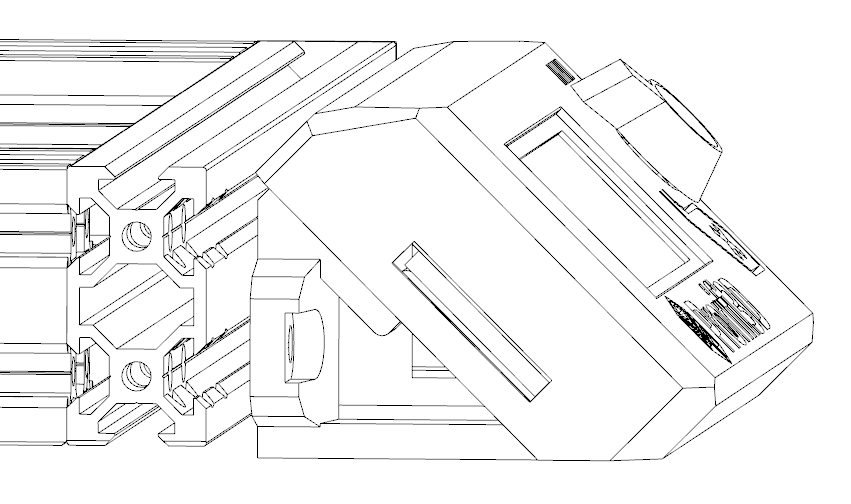
- Slide the Z motor mount into the slots from the top. Make sure you have the correct orientation.
- Press the printed part sideways against the profile and slide them to the position where printed parts are just about to touch the base, as shown in the picture below.
-
Tighten the screws to make sure it does not move freely. Do this for both left and right z motor mount.
-
Now carefully reinstall the X-axis, be careful with the linear bearings! You should lower the X-axis evenly. Do not proceed if you feel too much resistance or force, the linear bearings are very very easy to break!
-
Take the Left and right Z top, insert M5x10 flat head at the front and M5x12 flat head at sides. Hook hammer nuts on the screws and then install the Z top. The Z steel rods should be in the slots on the Z top and will not fall out. Then tighten all the M5 flat head screws.
Use M4x5 set screws to fix the back end of the Z top.
- Do this for both left and right sides.
4.2 Z motors
-
Now it is time to install the Z motors. Make sure you have the correct Z motors. The one with shorter wires should be closer to the control box! (which is at left when viewing from the front)
-
Put the motors in from the bottom. Rotated the leading screw evenly to allow the motors to be in position. The printed parts have slots for wires to pass through. Make sure no wires are clamped or twisted.
Use M3x12 screws to fix the motors. You should tighten the screws evenly in a diagonal order.
Install the Bottom cover at the end of the gantry beams and fix them with M4x5 set screws on both left and right sides.
- Collect the wires and proceed to the next step
4.3 Y-axis
-
Take the 4 Y rod holder, insert the square nut and pre-install the M3x12 set screws (the longer one) Make sure you have the correct orientation of the set screws
-
Install Y rod holder, be careful with the orientation.
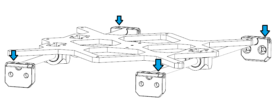
- Use the positioning jig and hex key to slide the T nut to the correct position. Place the T-nut to where the screws holes hould be. Do this for all 4 positions.
-
Now carefully put the entire Y-axis back from the top. Slide Y carriage to make sure the movement is smooth.
-
Now use the M5x10 button head to fix the left 2 Y rod holders. If you feel the T nut is not in position, try using the hex key to help align the T-nuts first.
- Slide the Y carriage back and forth to make sure the right Y rod is in the ideal position.
- Tighten the screws of the 2 right Y rod holders
-
Slide the Y carriage back and forth and check if it moves smoothly. If not, untighten the screws on the right 2 Y rod holder and repeat the previous 2 steps to make sure the Y rods are parallel to each other.
-
Now take the Y motor mount and Y motor, first install the Y motor to motor mounts use M3x14 screws, make sure the wire comes out from the bottom
-
Now insert 3 socket cap M5x10 screws into the Y motor mount.
-
Adjust the pre-inserted T-nuts to an ideal position, hook the T-nuts with the M5 screws on your Y motor mount.
-
Slightly tighten the screw to make sure the printed parts do not fall off, make sure it can still move freely
-
Use the jig as shown to position the Y motor mount.
-
Press the printed part against the base and tighten the screws.
- Take out the Y-Belt-Idler-A, Insert one nylon nut as shown
- Insert another nylon nut here
-
Insert 4 socket cap M5x10 screws. Hook the T-nut with the screws and then use the motor jig to position the idler.
-
Press the printed part against the base to make it parallel to the reference surface and tighten the screws.
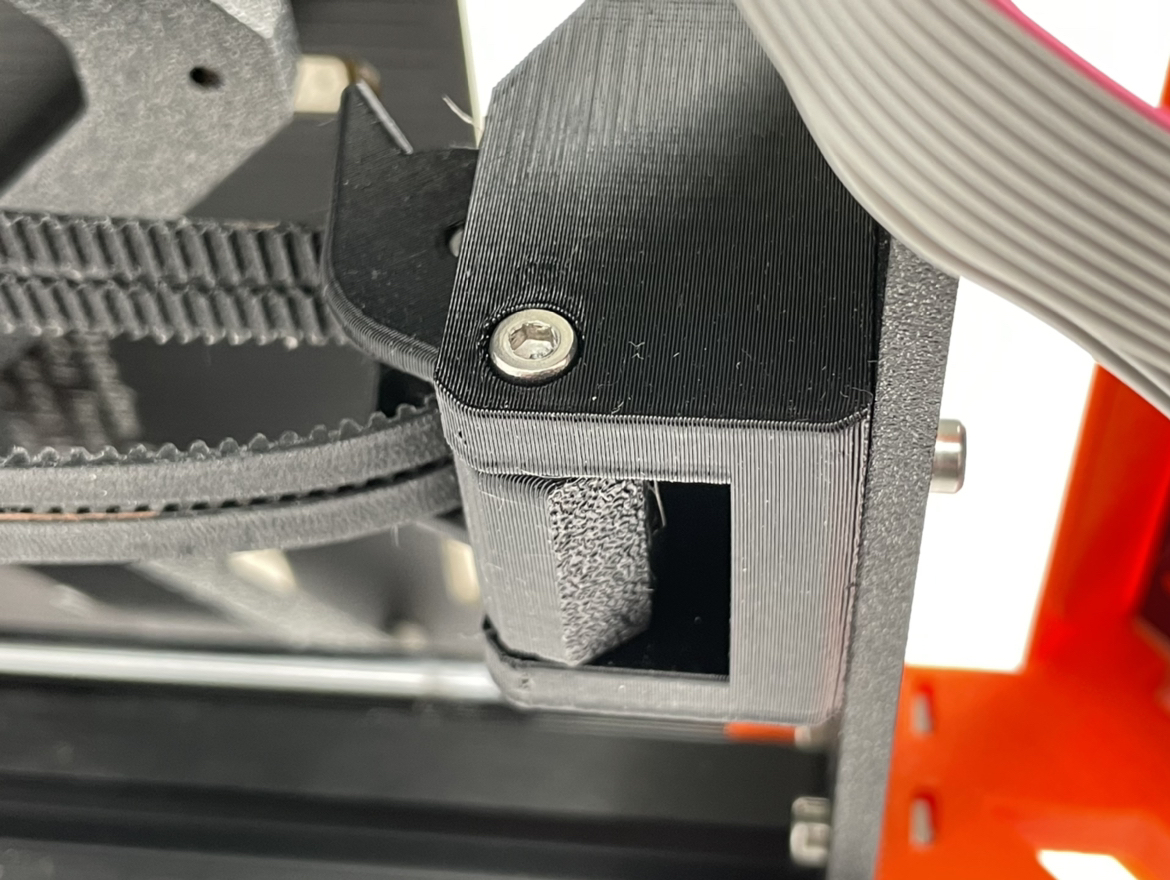
4.4 The control box
- Take the Electronics-Cover-Holder-C, insert 2 M5x10 button cap screws and hook the hammer nut on the screws. Install them at the back of the left gantry beam. Note the printed part surface should be at the same level as the base.
-
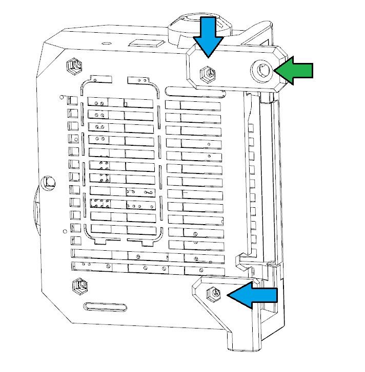
You can reuse most of your old control box. However, there are some additional parts.
-
Insert the hex nut into these positions and change the screws to M3x15 at these positions.
-
Insert one flat cap M5x8 screw, then hook 1 hammer nut on the M5x8 screw.
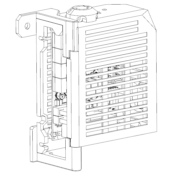
- The final control box should look like this.
4.5 PSU
- Take the PSU and PSU-Holders, Install the holder on PSU with M4x8 countersunk screws
- Install M3x6 screws here and hook the M3 hammer nut at the back If you have the black PSU
- Insert M3x8 screws here and hook the M3 hammer nut at the back If you have the old version silver PSU. Replace the old bottom cap with the new one so that wires can go from the bottom.
- Install the PSU on the frame, make sure the screws are tightened properly
4.6 LCD
-
Take the LCD supports, the installation for LCD support is the same as original ones. You can refer to the guide here: https://help.prusa3d.com/en/guide/6-lcd-assembly_172423
-
Connect the electronics first, make sure you have the correct wires.
-
Use the M5x10 button cap screws and hammer nut to fix the LCD on the main frame. The wires should be able to bend and go through the bottom of the base.
4.7 Endcaps
- Install the endcaps with M4x5 set screws
5. The Dual Belt Plus system
5.1 Remove the original Y axis parts
-
Turn the printer sidewise, make sure the printer stay still
-
Take off the original Y belt holder and the orignal Y belt from the Y carriage
5.2 Install the new Y-Belt-Holder-A
- Take the Y-Belt-Holder-A and install it to the Y carriage using two M3x10 screws as shown. Make sure you have the correct orientation.
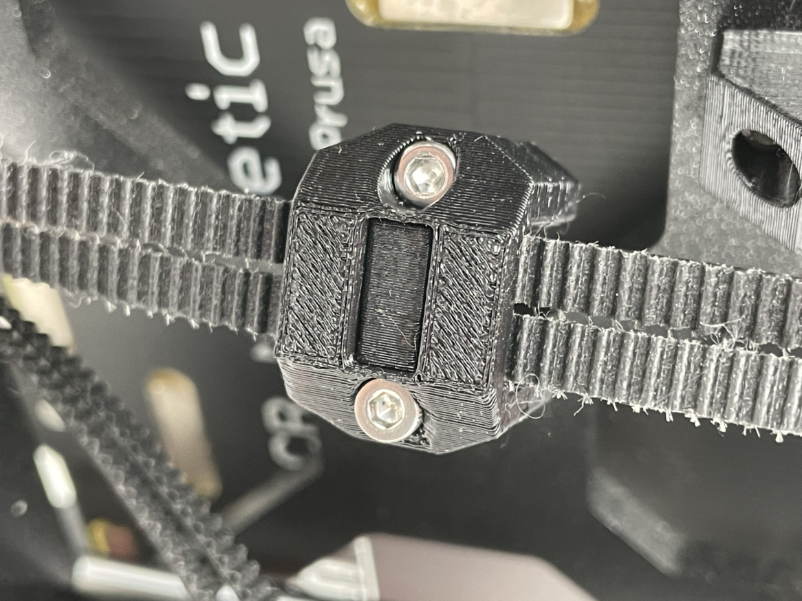
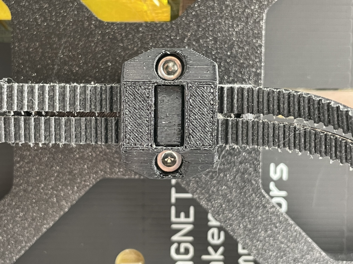
5.3 Assemble the Y tensioner
If you have the older Dual Belt instead of Dual Belt Plus, please refer to the archive here
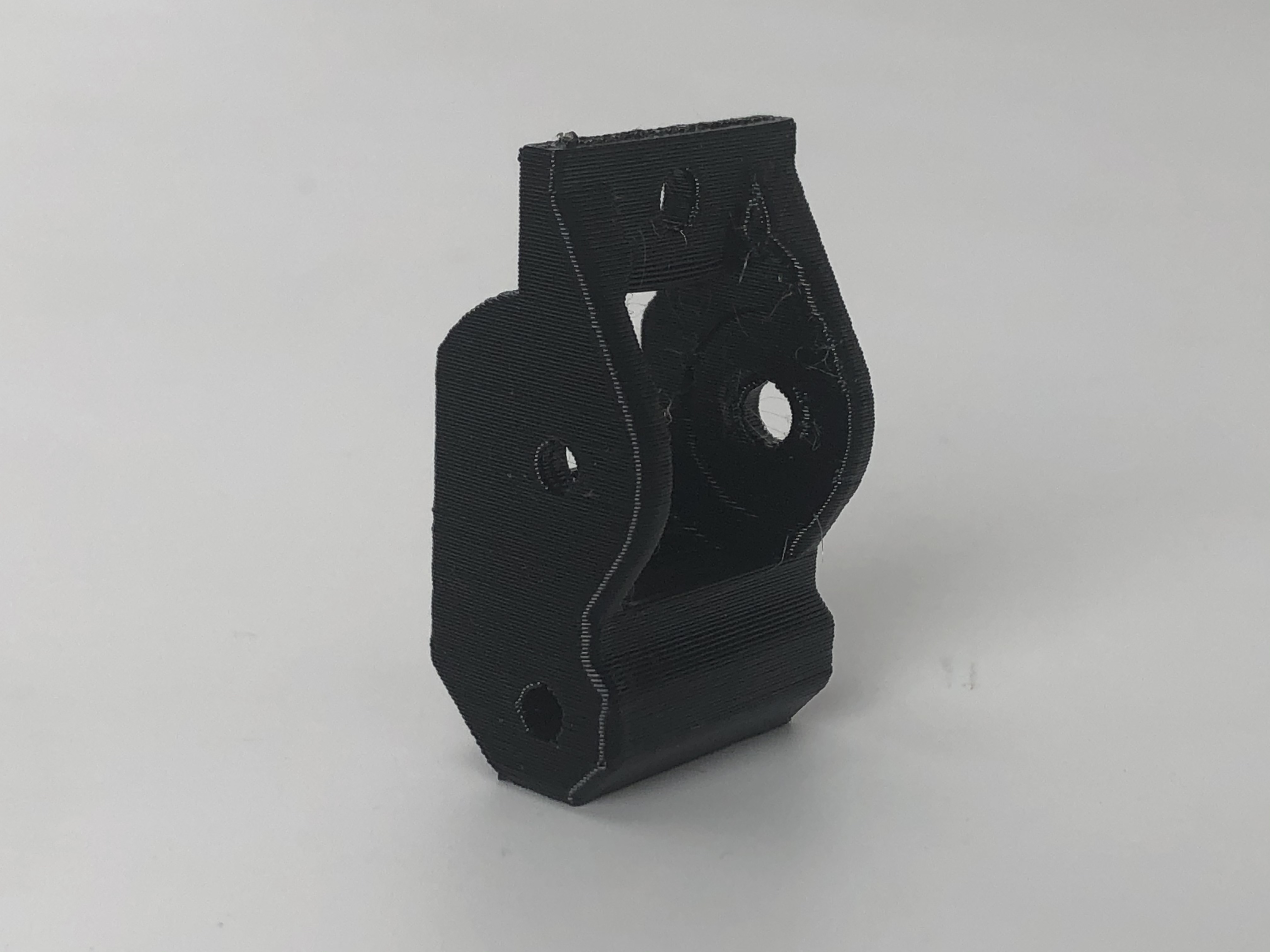
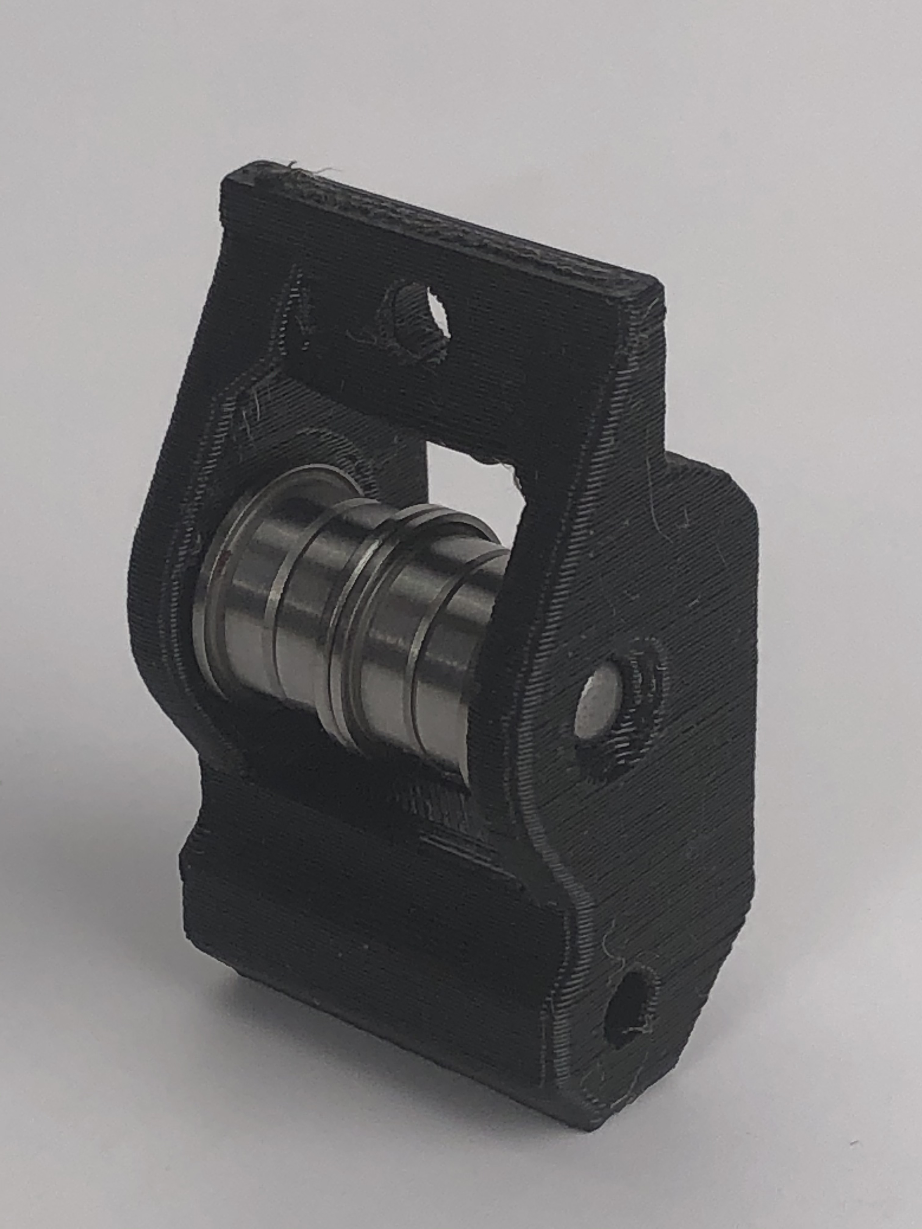
- The printed parts should look the same as shown in the picture. Note that this part is not symmetric.
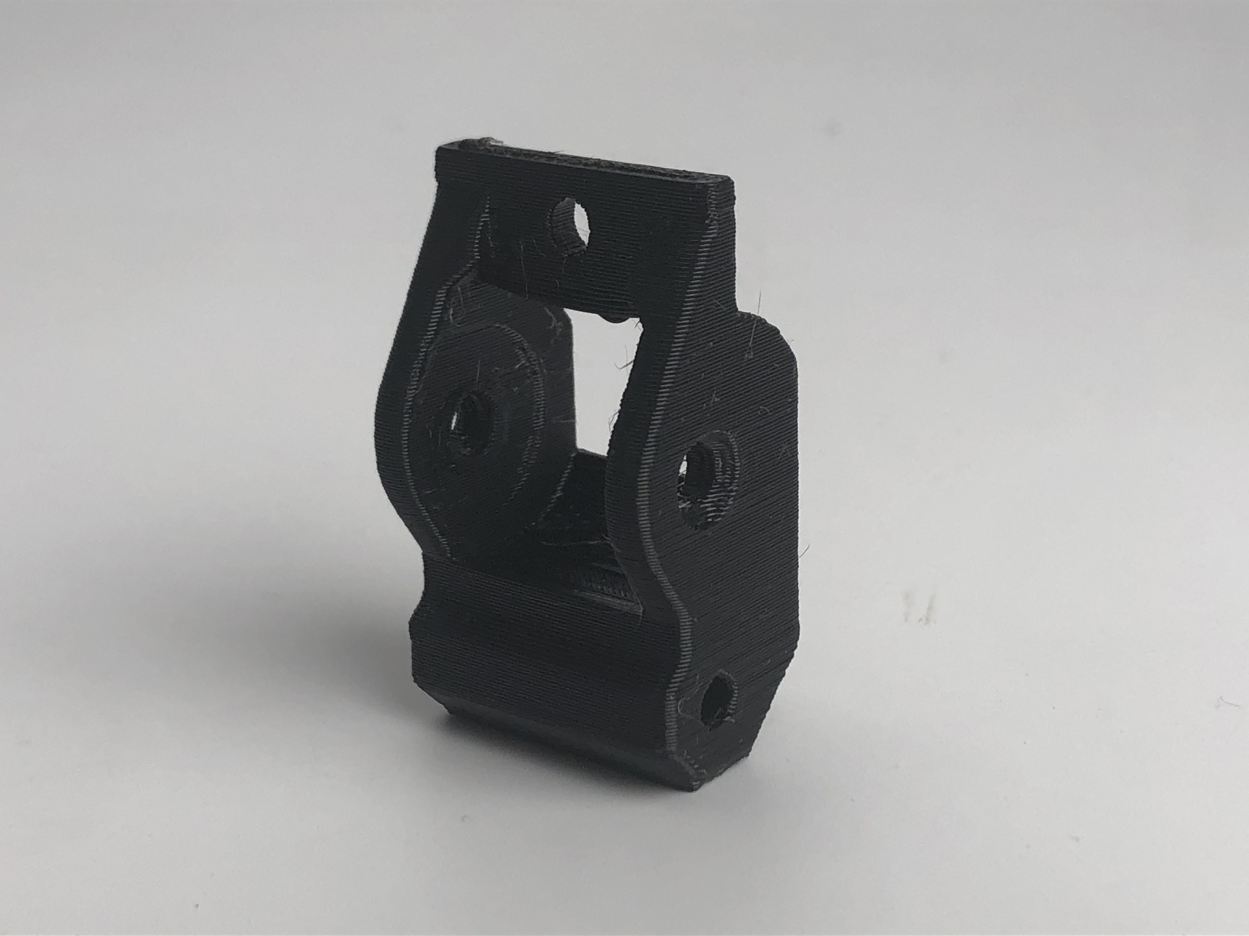 |
| 
-
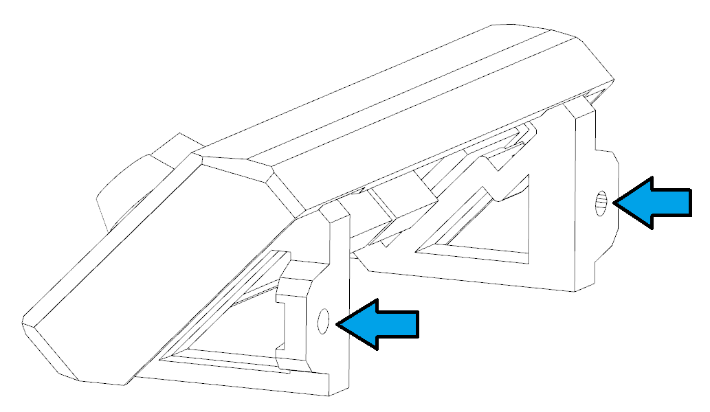
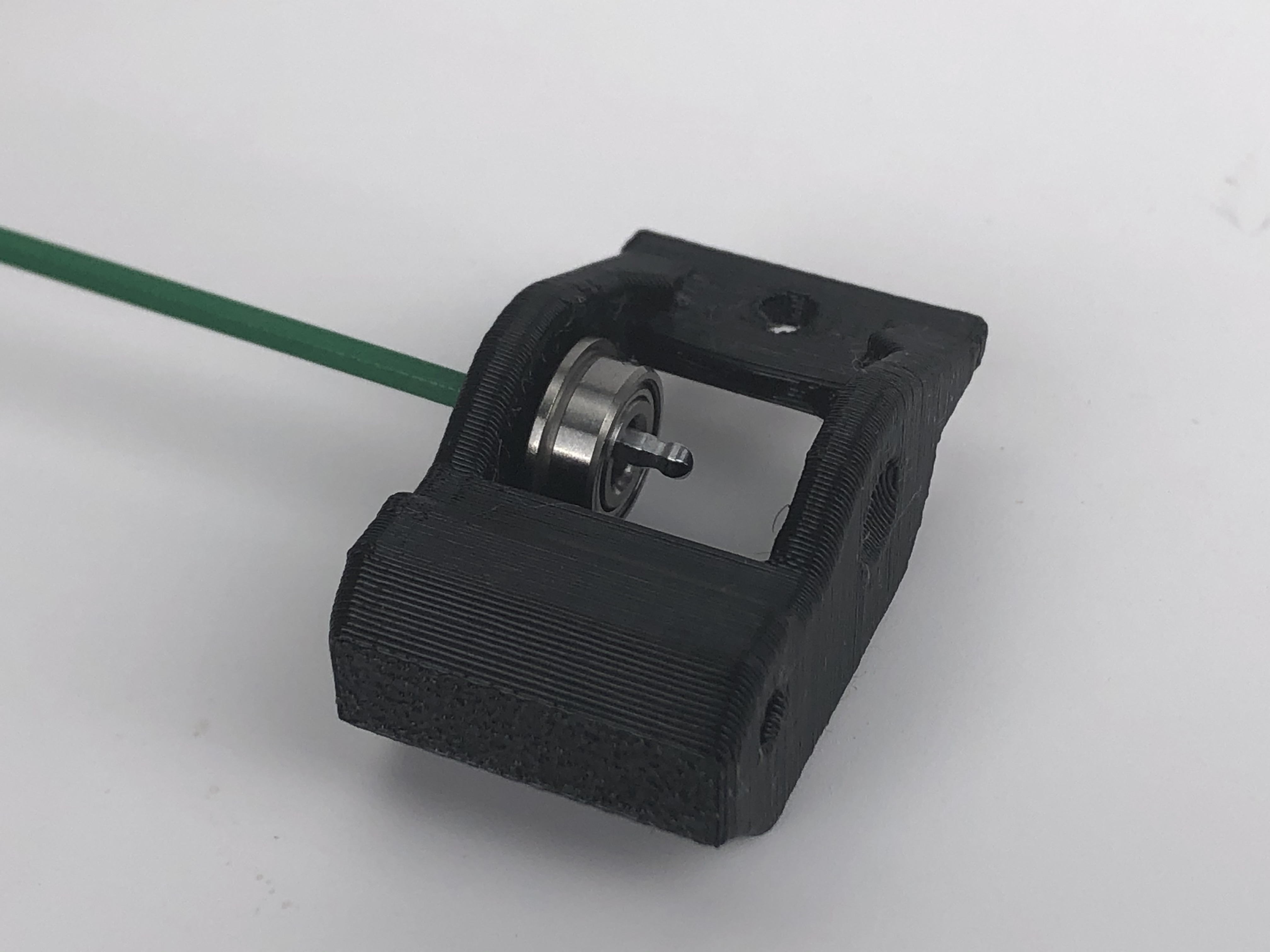
Insert your hex key into the Y tensioner and place the bearings on the hex key one by one as shown. Guide the bearings and insert the hex key all the way through the Y tensioner. Note that you shall insert from the side which is not chamfered.
-
-
The bearings should look as shown.
-
-
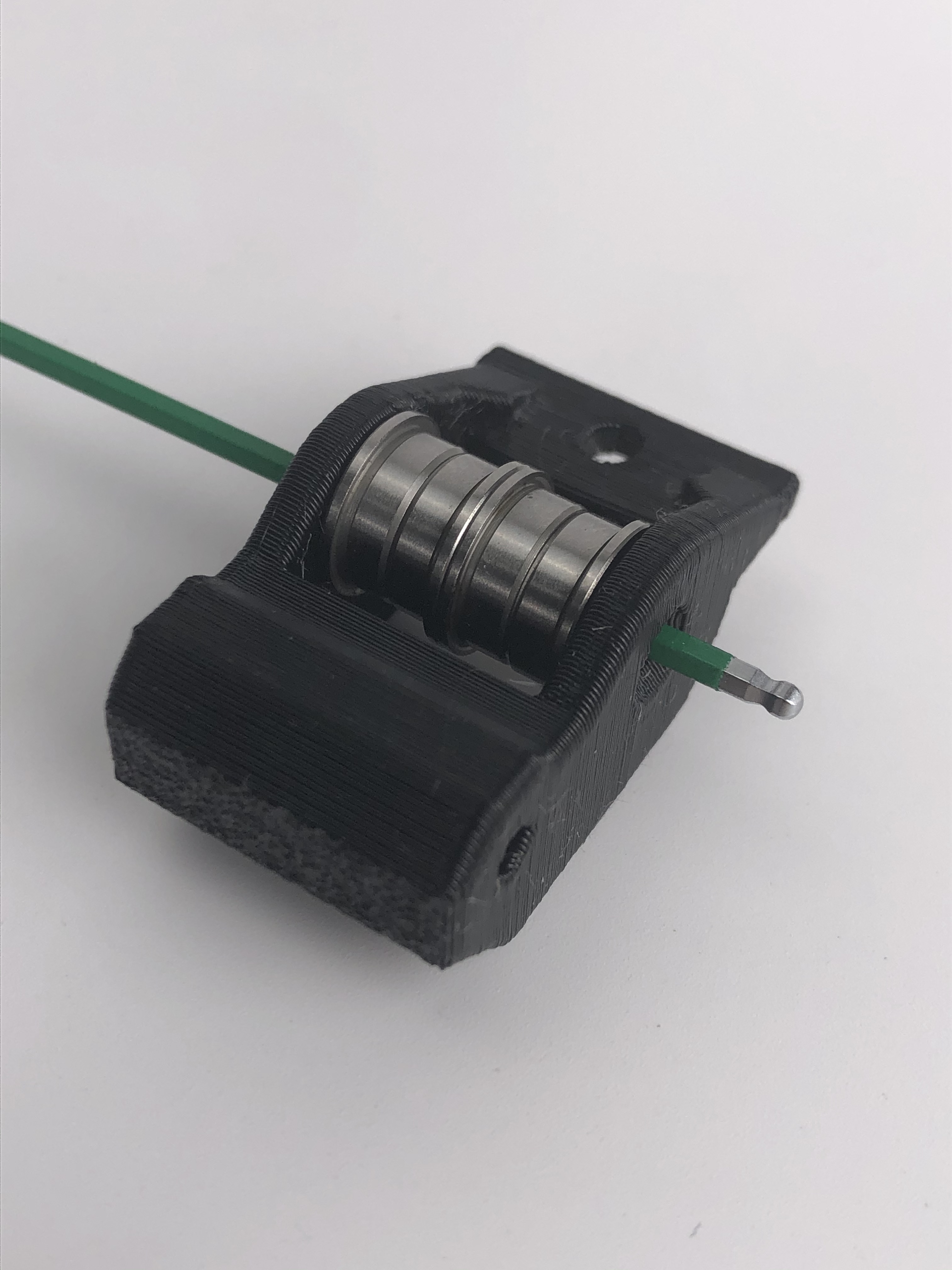
Now, insert the pin from the chamfered side and use the pin to replace and push the hex key out of the bearings.
-
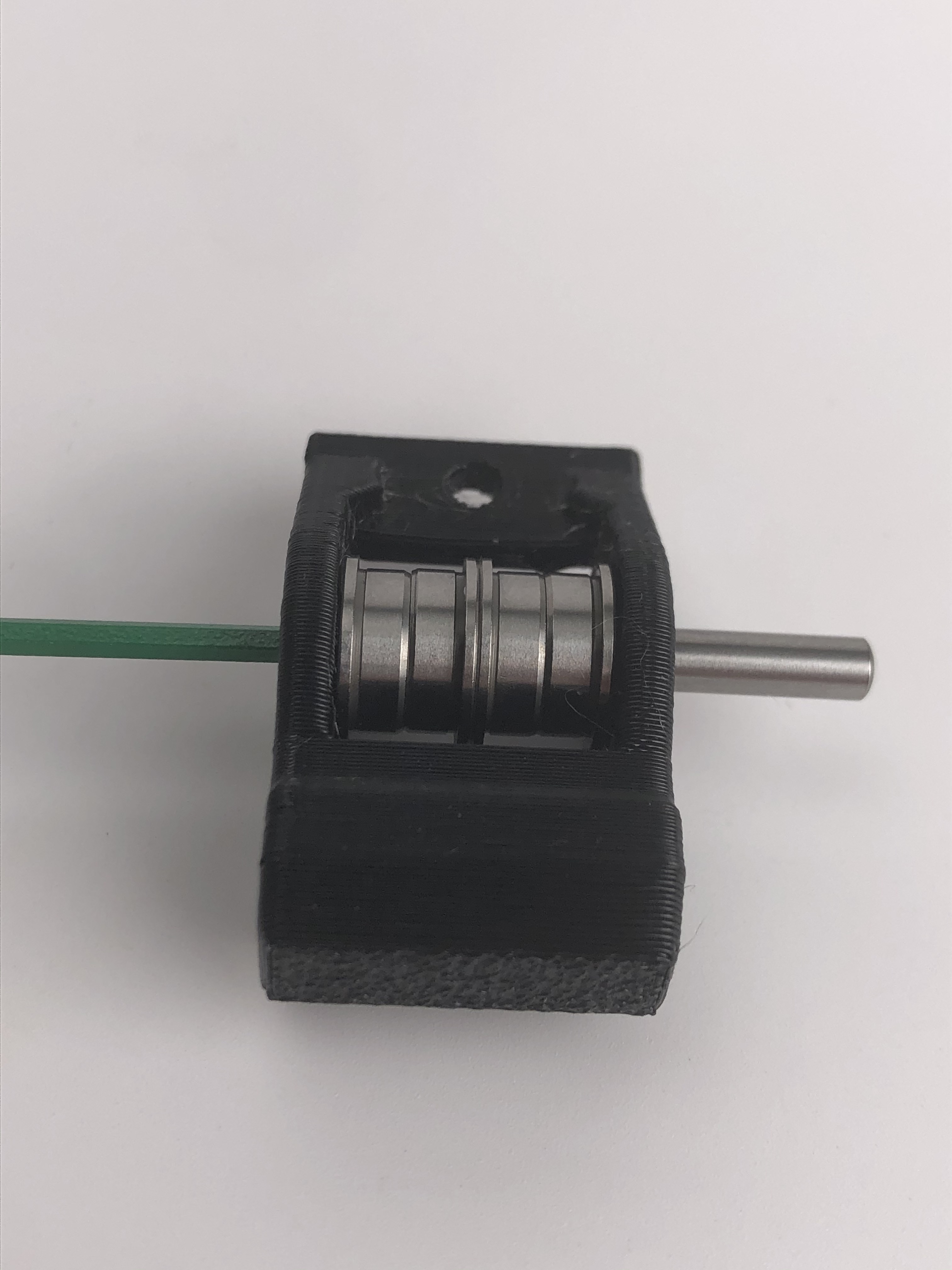
Insert the pin all the way to the end. Use a 3mm hex key to assist and make sure the pin is at the end.
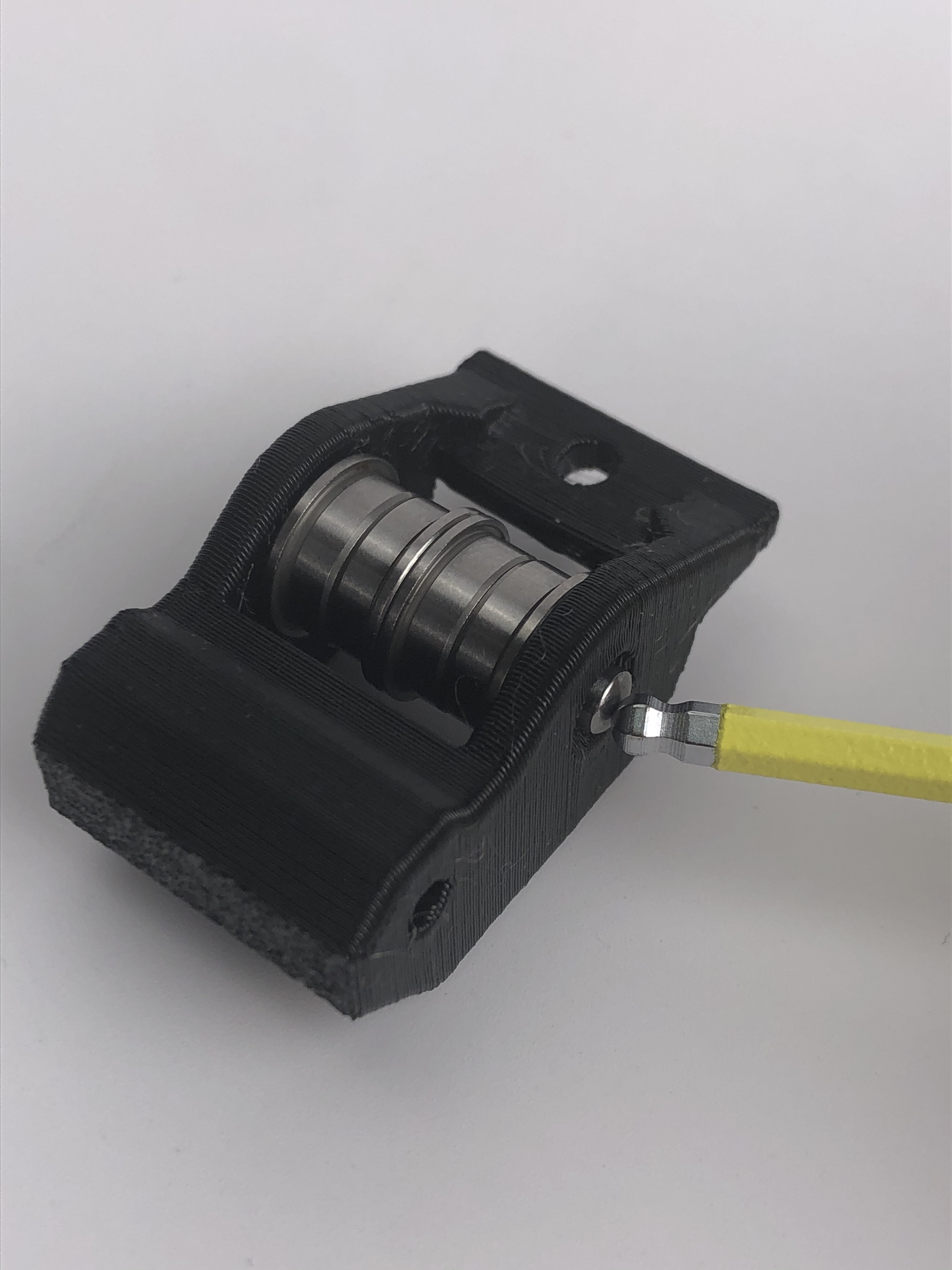
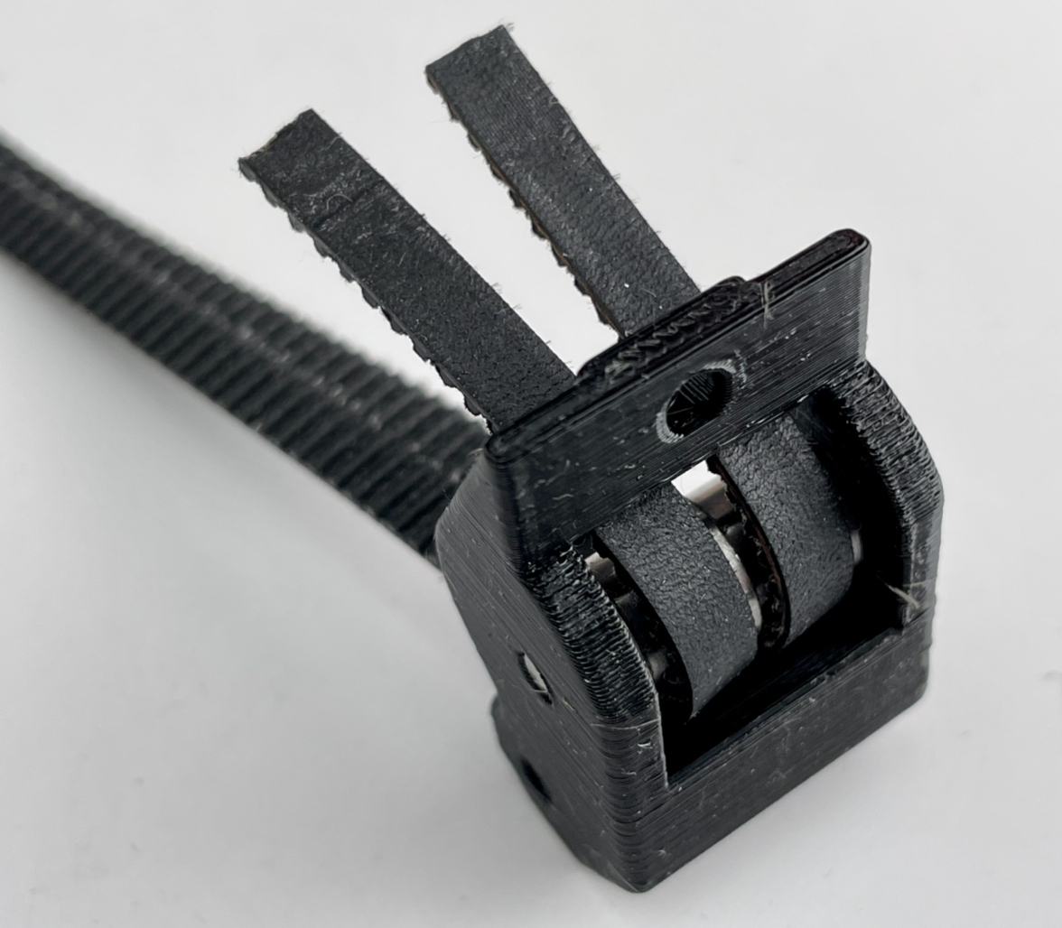
The new Dual Belt Plus tensioner is complete!
-
-
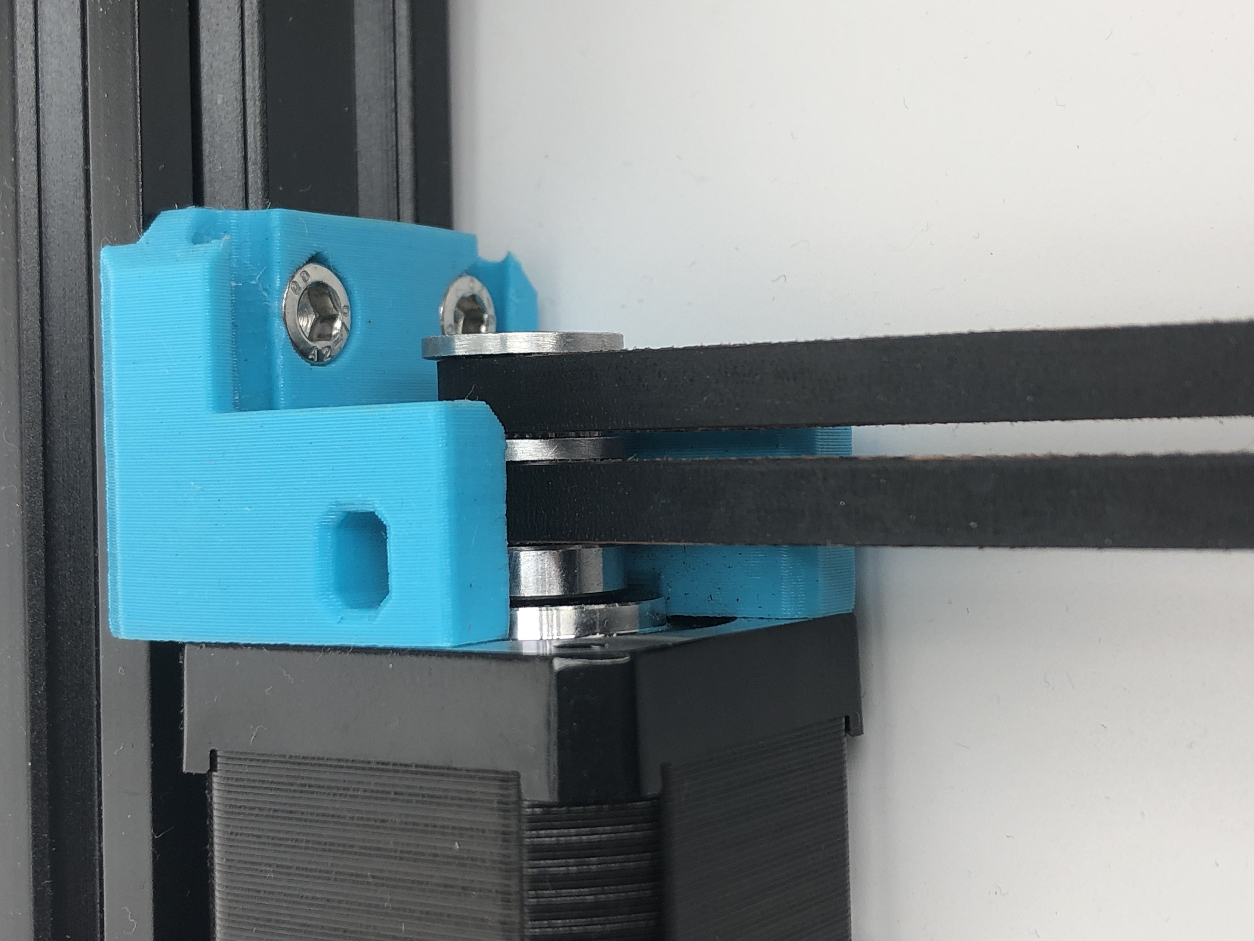
Pass the two belts through the Y tensioner as shown.
- Connect the timing belt as shown. Make sure the belts reach the end. Otherwise, the belt length will be different.
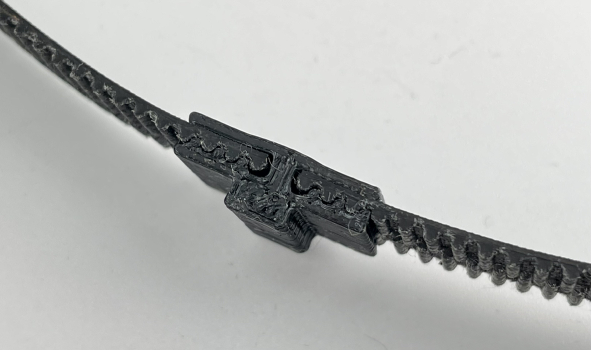
Insert the M3x32mm screw(the longest one) into the Y tensioner.
- Install the timing belt into the Y-Belt-Clip as shown. Put 2 M3x12 screws in advance.
-
Put Y Belt Clip into Y Belt Holder B, the upper cover of the Y holder.
-
Attach Y Belt Holder B to Y Belt Holder A. Make sure you turn the screws on both sides evenly in turn.
5.4 The final assembly
- Put the Dual belt driving pulley on the Y motor shaft, as close to the motor side as possible, leaving a very small gap only. Make sure the pulley is not touching the motor.
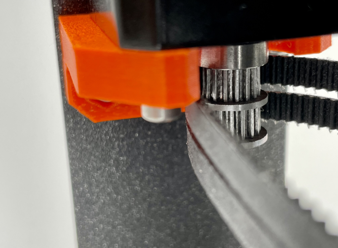
- Put the timing belt around the pulley, let the teeth match the belt
-
Install the adjusting screw(M3x12mm) and leave a proper distance. If the belt does not fully match the driving pulley or the left and right belt does not have the same tension. Just move the Y carriage back and forth when the belt is under tension until the two belts are working properly.
-
We will fine tune the belt tension later according to the printing test.
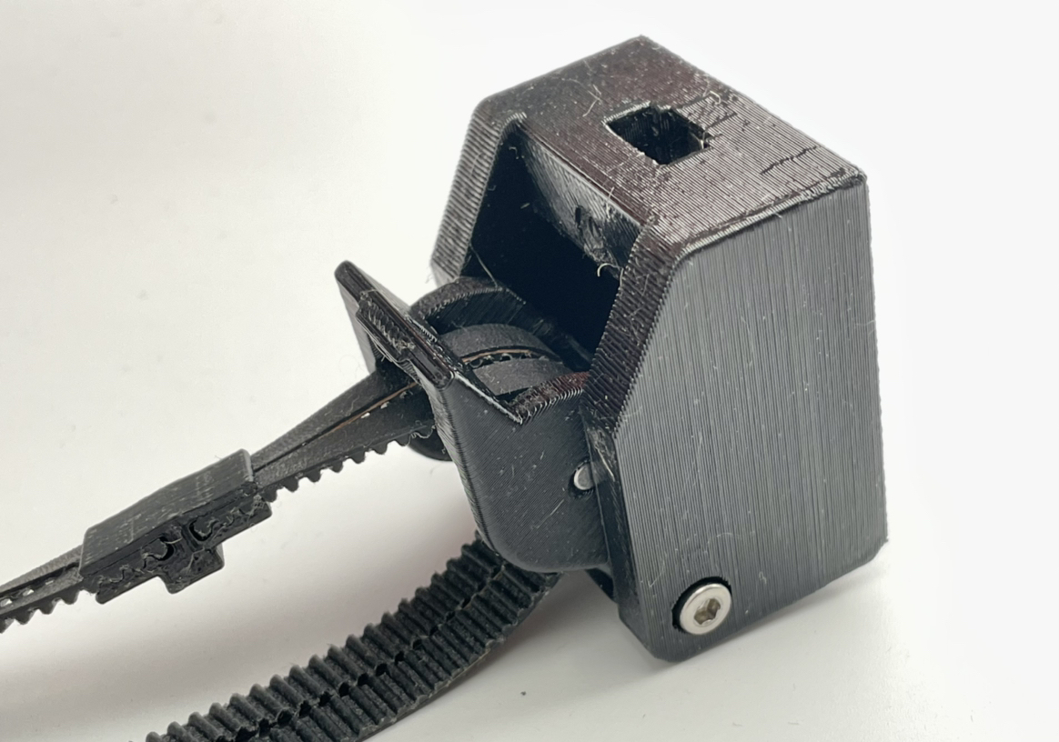
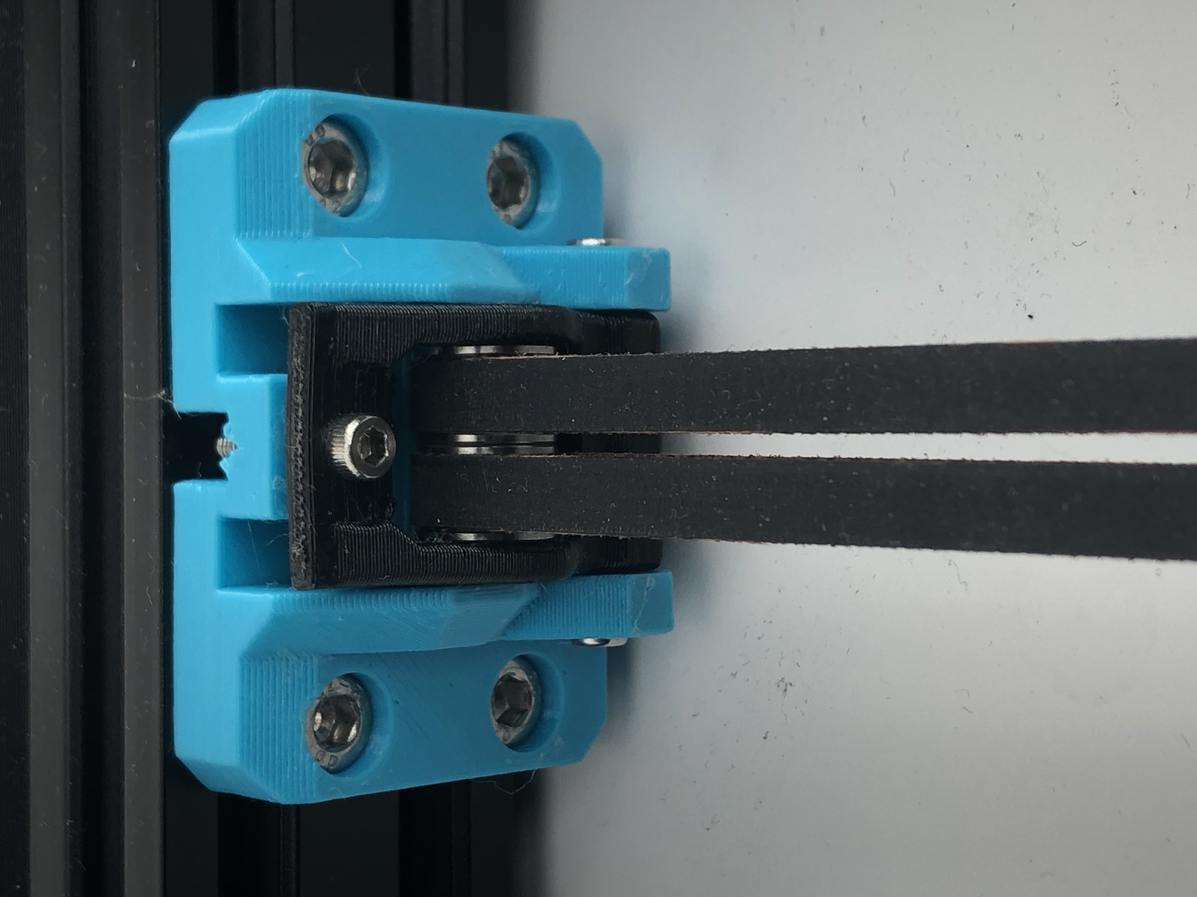
- The Y tensioner should be installed as shown.
6. Replace the E motor (additional)
Prorifi3D E motors have the same dimension as the original one. It is a direct replacement. You can refer to this section to rebuild the E axis:https://help.prusa3d.com/en/guide/5-e-axis-assembly_28536
7. Electronics
-
The electronics are the same as the original i3. You can find the reference here:https://help.prusa3d.com/en/guide/8-electronics-assembly_34416
-
Do this before install the control box
8. Install the control box
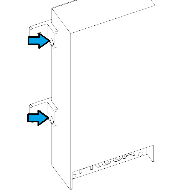
- Hook the control box on the holder as shown.
- Tighten the screws.
9. Spool holder
- Install the spool holder with flat cap M5x10 screws and hammer nuts.
10. Performance boost
10.1 Install the heat sinks
-
To get an extra performance boost, you can install the heatsink first. This will lower the motor running temperature, allowing a larger current and better stability.
-
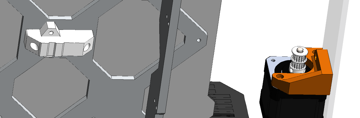
For Y motors we recommend you install as shown:
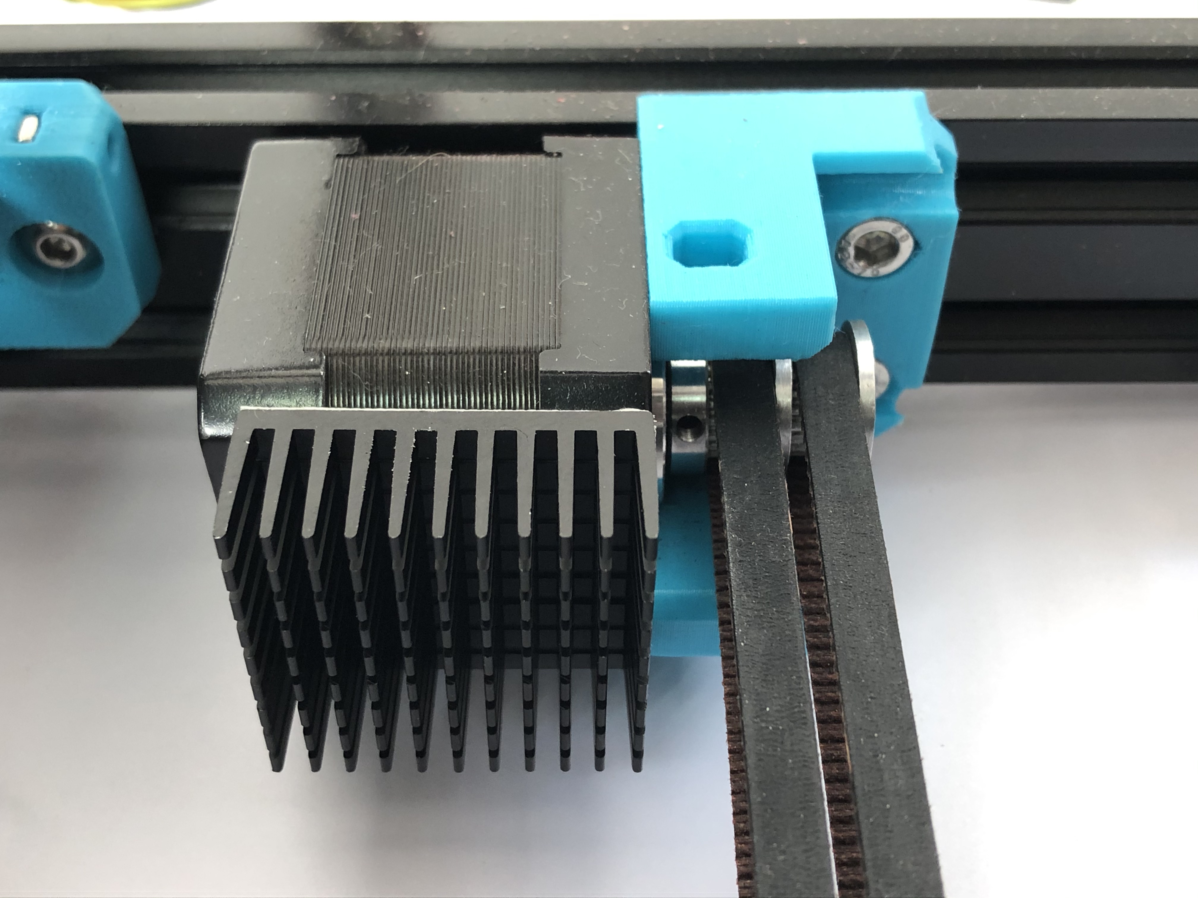
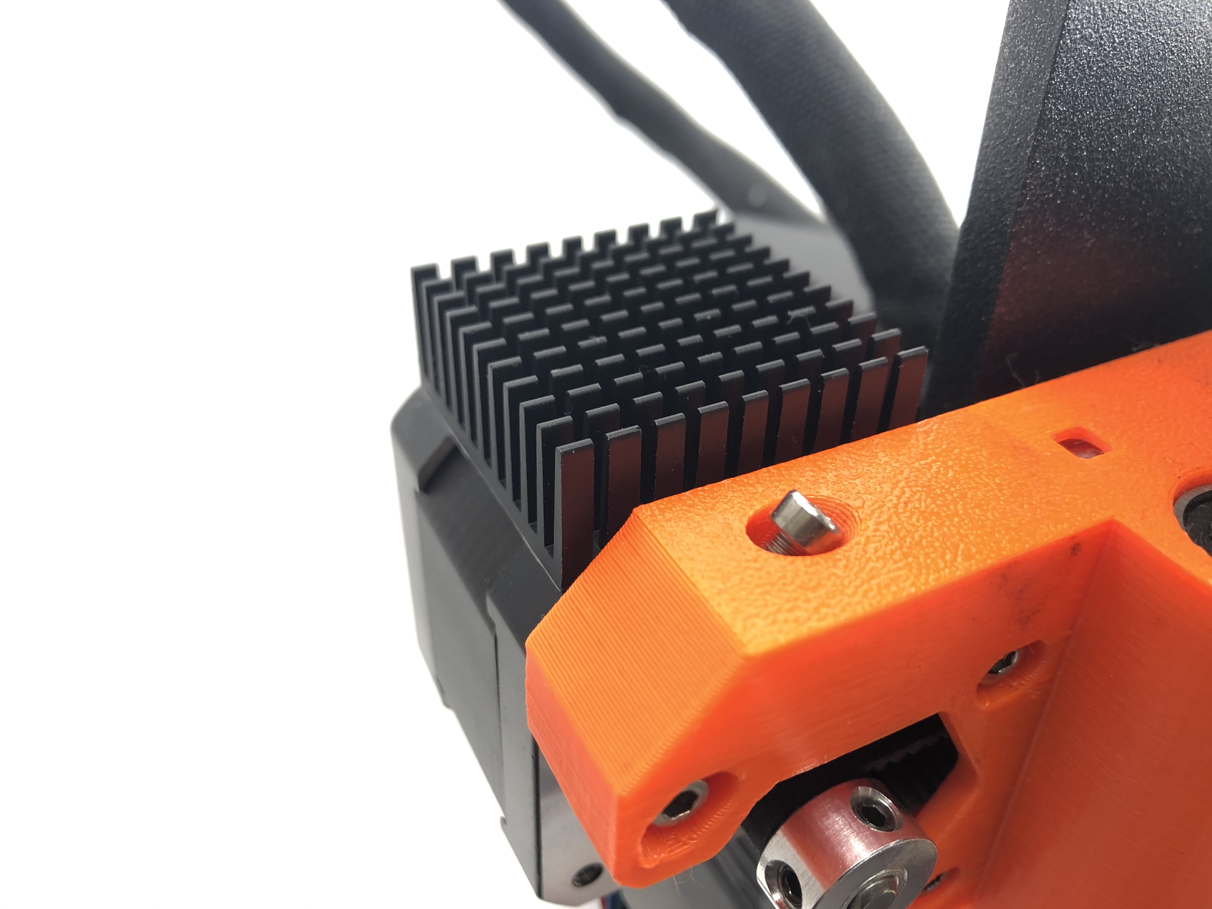
- For X motors we recommend you install as shown:
10.2 Changing the motor current
-
You can change the current via Gcode
-
First, connect your printer using USB cable
-
Use Pronterface to connect your printer
-
Change the RMS current of your XY motor using
M907 X520 Y520
- Change the steps per unit distance using
M92 Y80
- Save the settings by typing
M500
11. Belt tension adjust
-
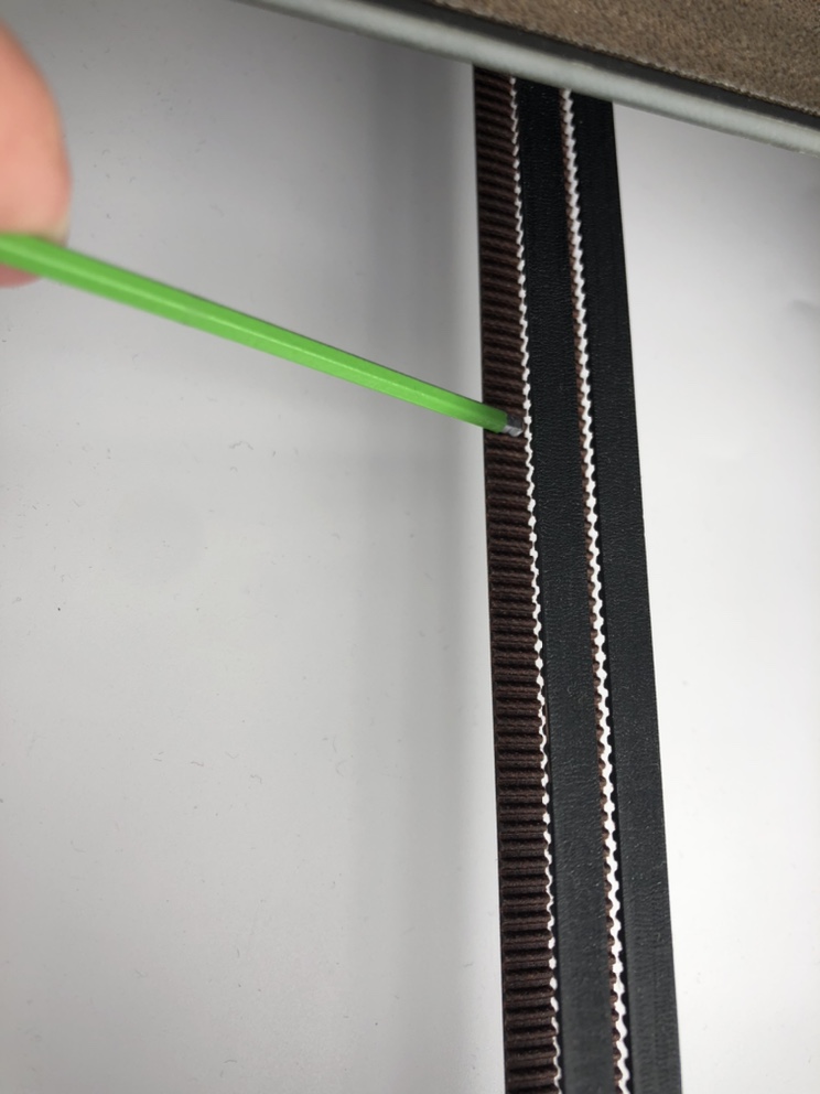
First set your belt to the lowest tension. You can use phone apps to determine the vibration frequency of your belt. The minimum value should be about 54Hz.
-
You can use phone apps to measure the belt vibration frequency.
-
When measuring the belt frequency, push the heated bed all the way to the back (where the motor is). Slightly picking the lower belt in the middle as shown. You can use a hex key to assist. For the Dual Belt system you only need to pick one of the belts.
-
Slowly tighten the belt, we recommend you tighten the belt to around 80Hz. Which should give an overall good result.
-
Print the test block and you shall see no 2mm patterns and MRR should be almost gone.